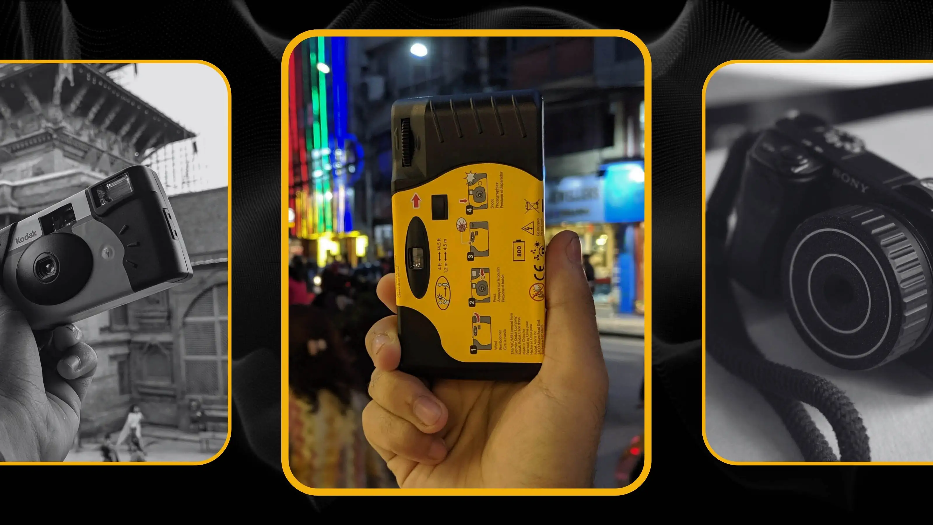
Designing something is rarely just about necessity—it’s about possibility. As a mechanical product designer, I’m often drawn to projects that allow me to dig in, experiment, and push the limits. When I first got my hands on the CMF Phone 1, with its interesting back panel and exposed screws, it felt like an invitation. This phone wasn’t just a tool; it was a challenge. I wanted to add a wireless charging to it and a unique charging dock, something that could support MagSafe, charge any other Qi-enabled device, and even include a secondary display – for fun.
I had a vision of a dock that could blend utility with a bit of flair, and the back panel of the CMF Phone gave me the perfect starting point. The journey wasn’t straightforward, and I encountered plenty of setbacks along the way, abandoning the whole idea about CMF Phone 1. Here’s how it unfolded.
Sketching and Conceptualizing: Imagining the Dock
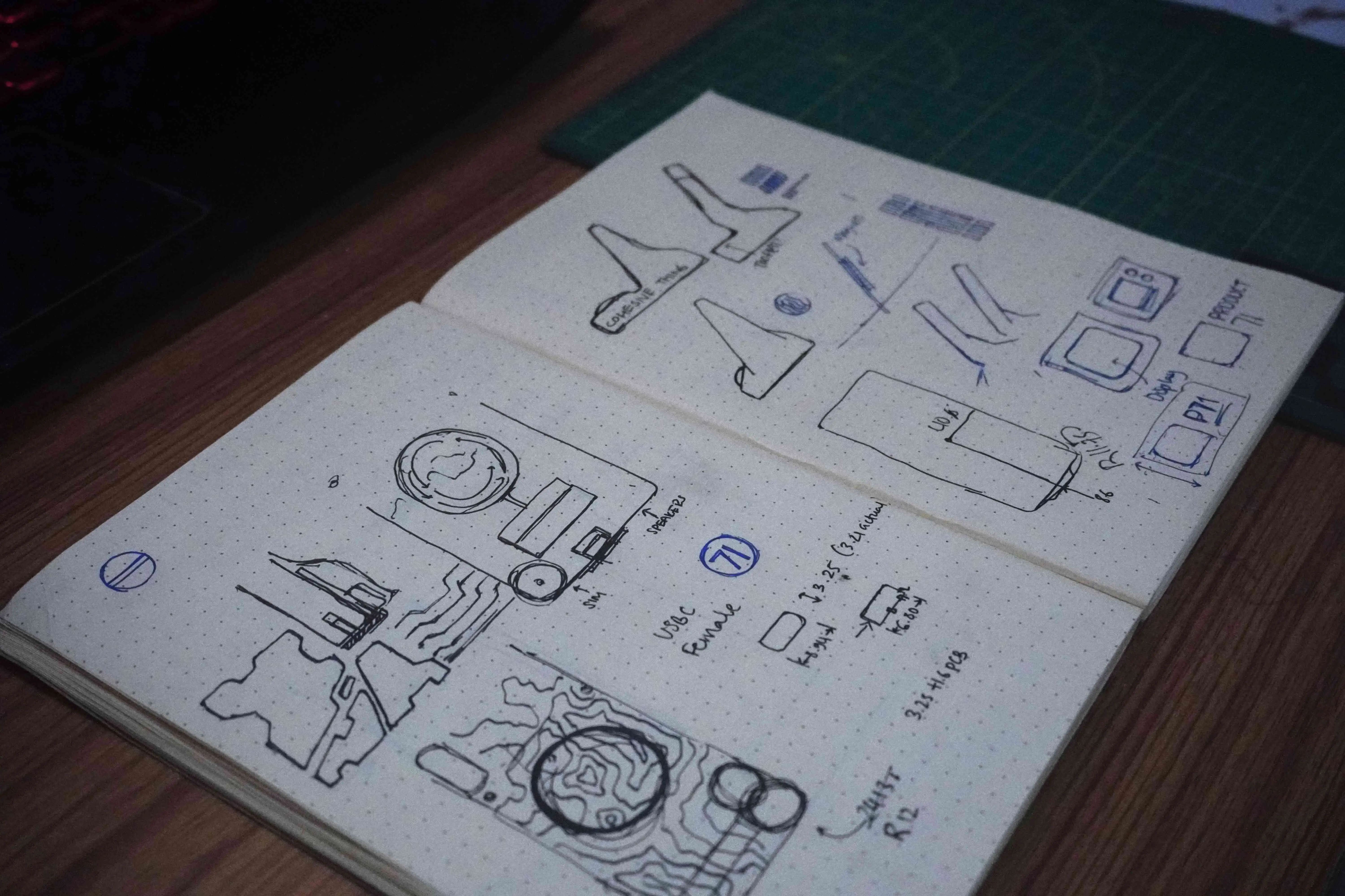
The first step was capturing that vision on paper. I wanted something sleek but substantial, a dock that could sit confidently on a desk or nightstand. I sketched out various ideas, playing with angles and base shapes. The idea was to make it functional yet visually appealing, with a clear layout for where the MagSafe magnets would sit and a slot for a secondary display.
I’ve always felt that good design doesn’t just solve a problem; it elevates the experience. So while I wanted the dock to be versatile, it was also about making a product that was enjoyable to use and intriguing to look at. These initial sketches helped me focus on what was essential and where I could push the design further.
Prototyping the First Builds
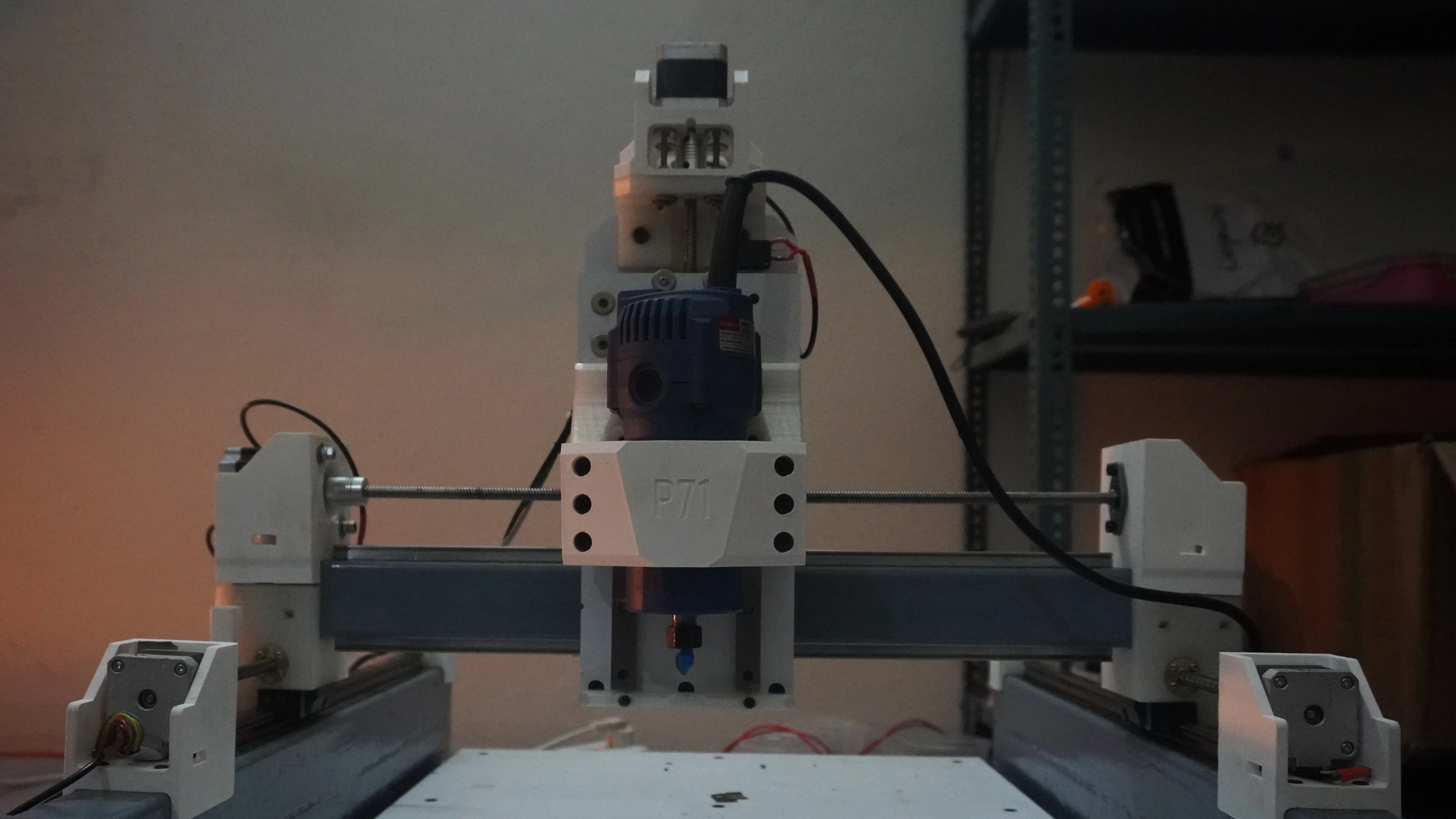
With my preliminary sketches in hand, I started translating the design into a digital model. Having worked on similar dock and stand designs before, I already had a strong sense of the ideal angles and proportions to make it functional and visually balanced. I spent time fine-tuning these details on screen, adjusting measurements and exploring different shapes to ensure it would feel intuitive and stable.
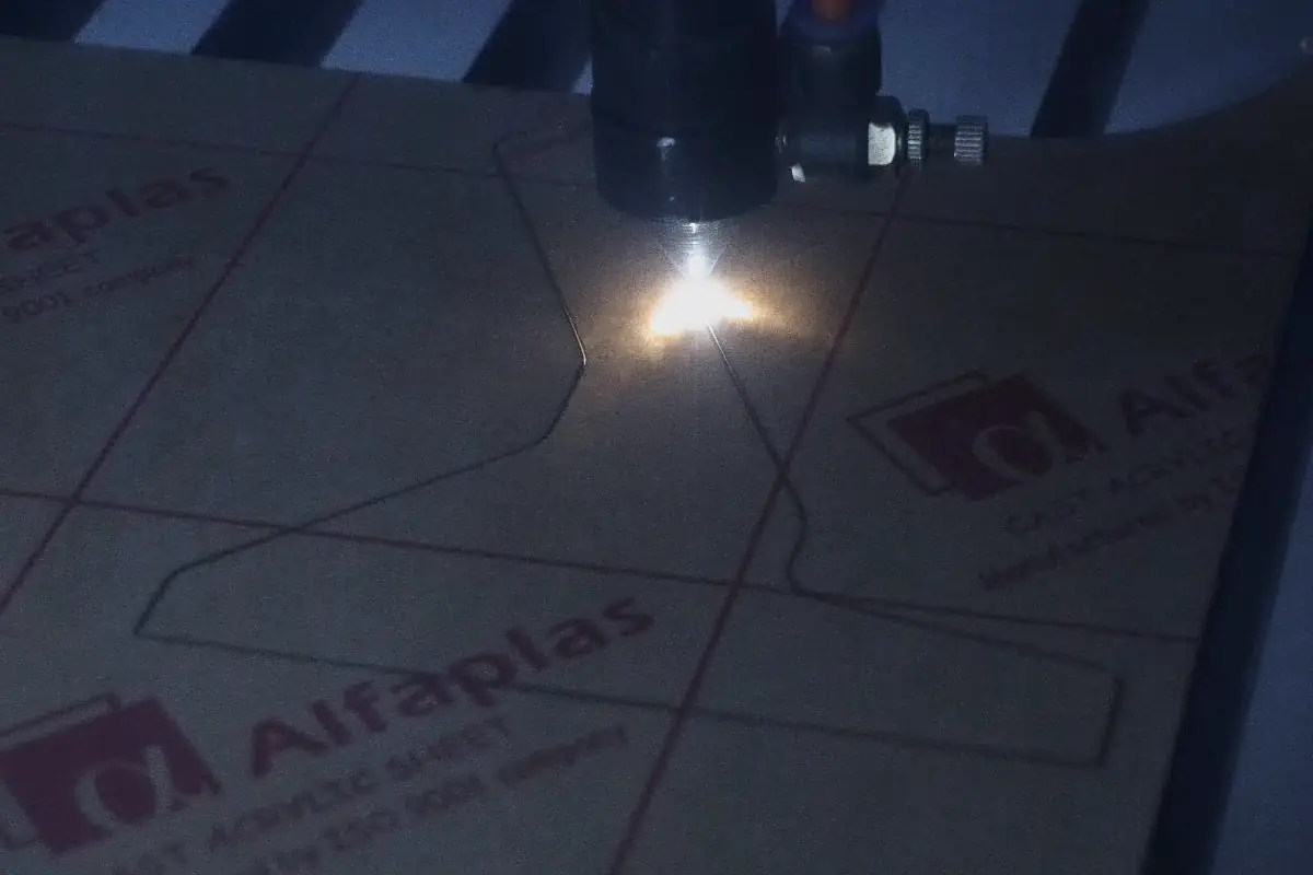
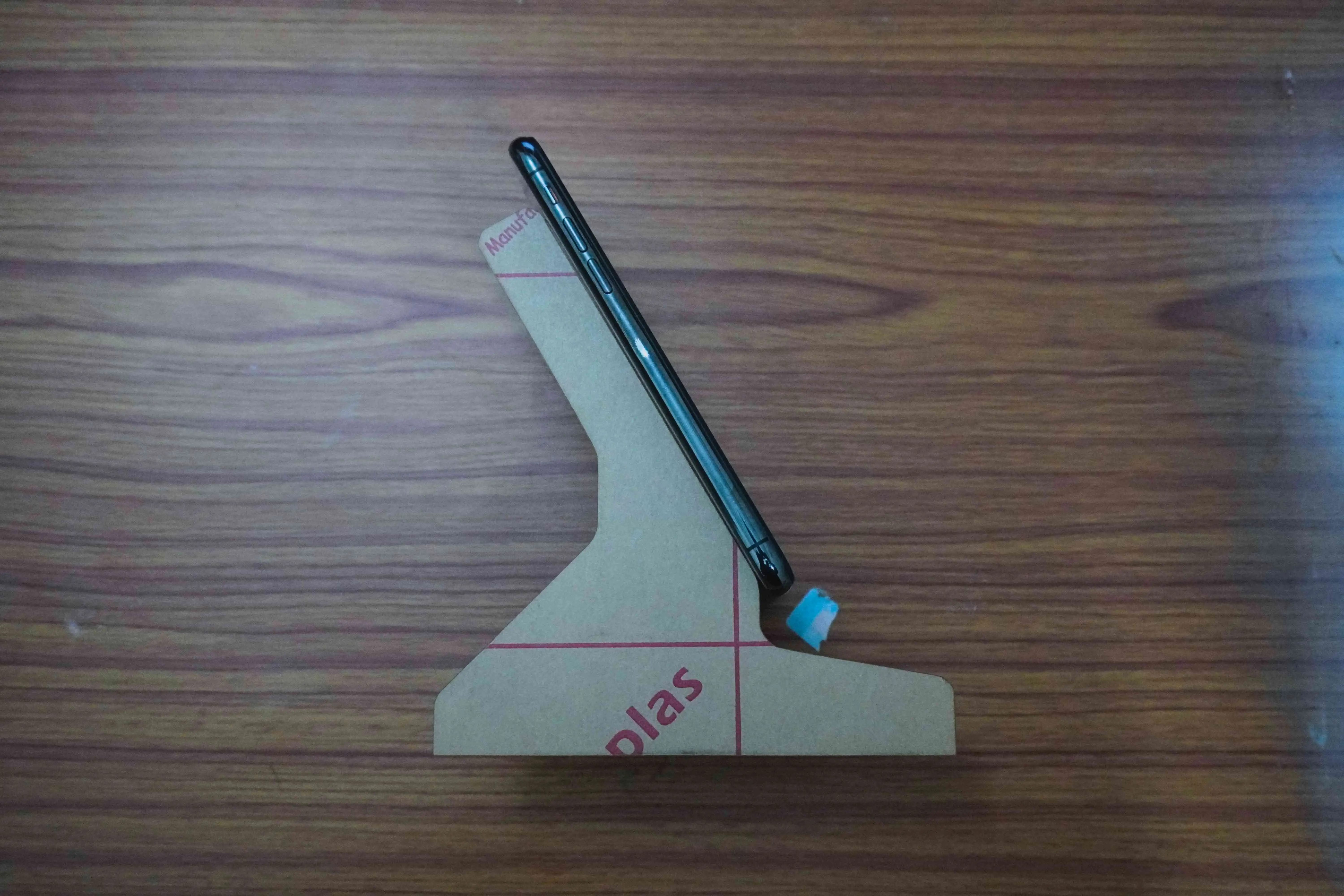
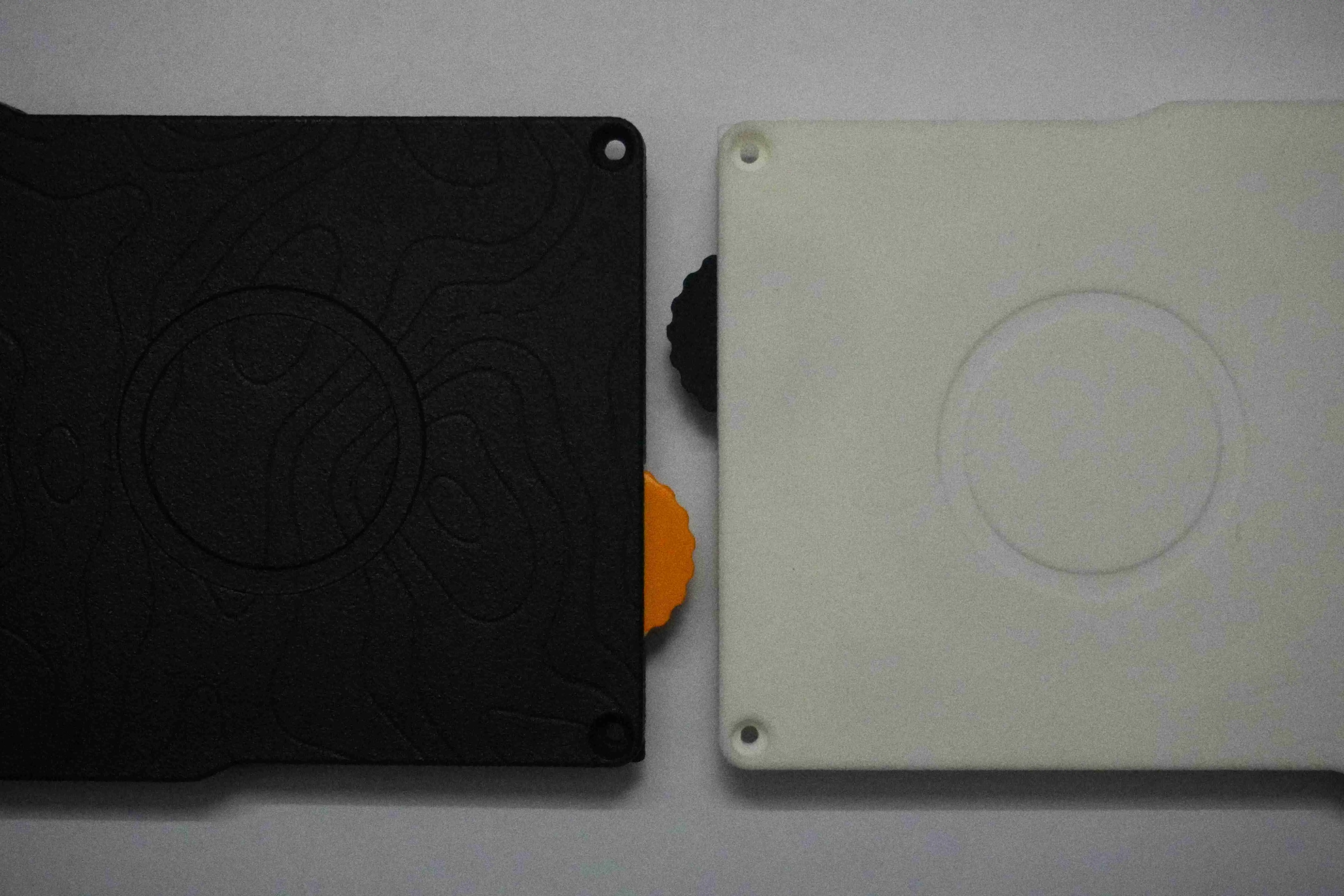
Before committing to a final design, I created a rough physical representation using a laser-cut side view model. This quick, low-cost approach allowed me to see how the dock might look and feel in real space, validating some of my initial design choices. Interestingly, the idea to incorporate a secondary display came later. During a discussion with a friend, he suggested adding a screen to display charging status or even simple animations. It wasn’t something I’d originally planned, but I saw the potential and decided to make room for it in the design. He also mentioned the possibility of integrating a speaker down the line, which got me thinking about how the dock could evolve.
With these new ideas, I adjusted the dock to allow for future upgrades, including mounting spaces for additional PCBs. For now, my main priority is to complete the core functionality—the wireless charger—but the design leaves room for future expansion as the project matures, one feature at a time. Once satisfied with the overall layout, I sent the design to JLC3DP for manufacturing.
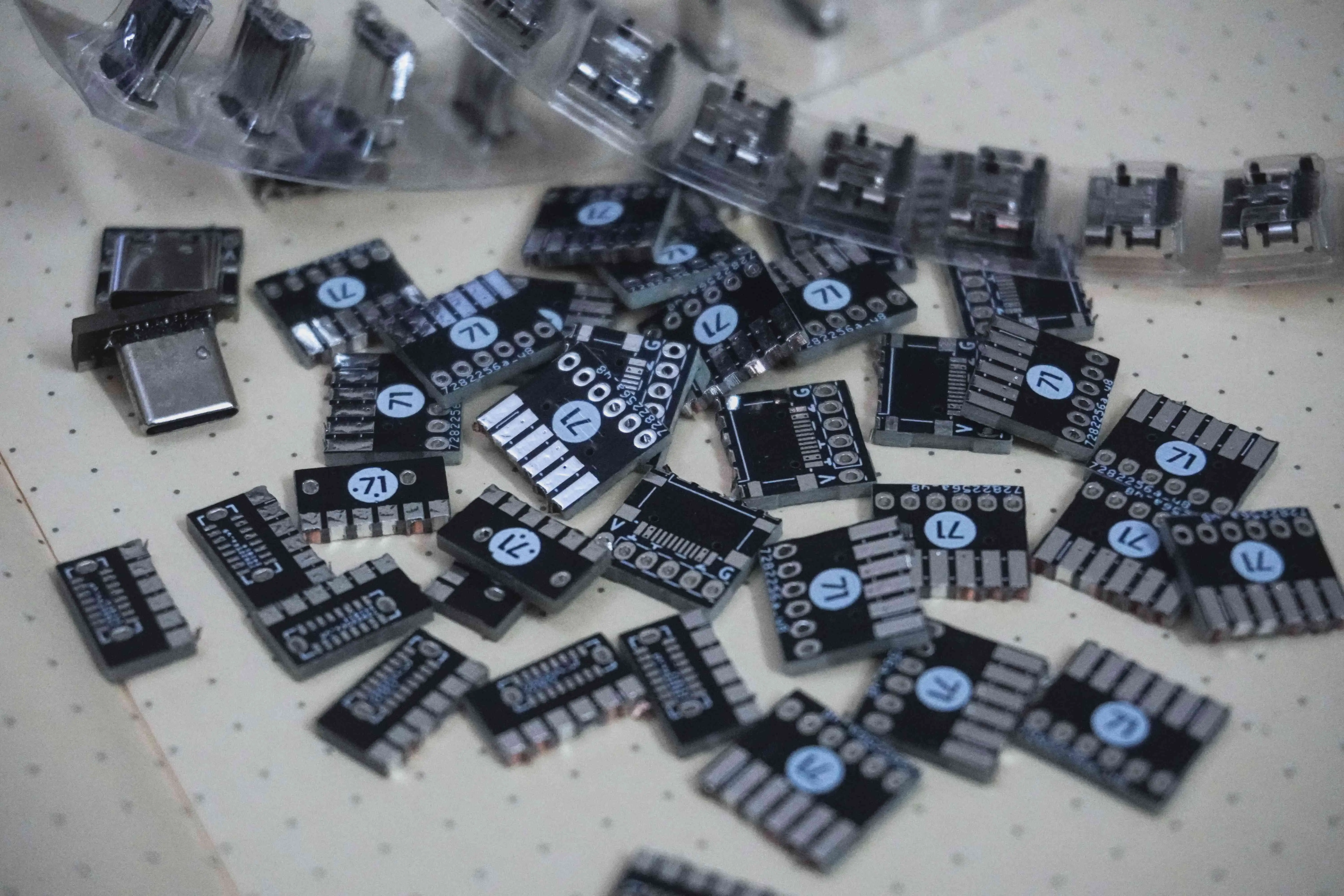
Precision Delivered: The Arrival of Custom Prints and PCBs
When the prints and PCBs arrived from JLC3DP, they exceeded expectations. Every detail, from the sharp edges of the PCBs to the smooth finish of the printed case, reflected the precision and reliability I’ve come to associate with their services. They were flawless in quality and exactly as specified. The excitement of seeing my designs take physical form was electric, setting the stage for the next steps in the project.

Hitting a Roadblock
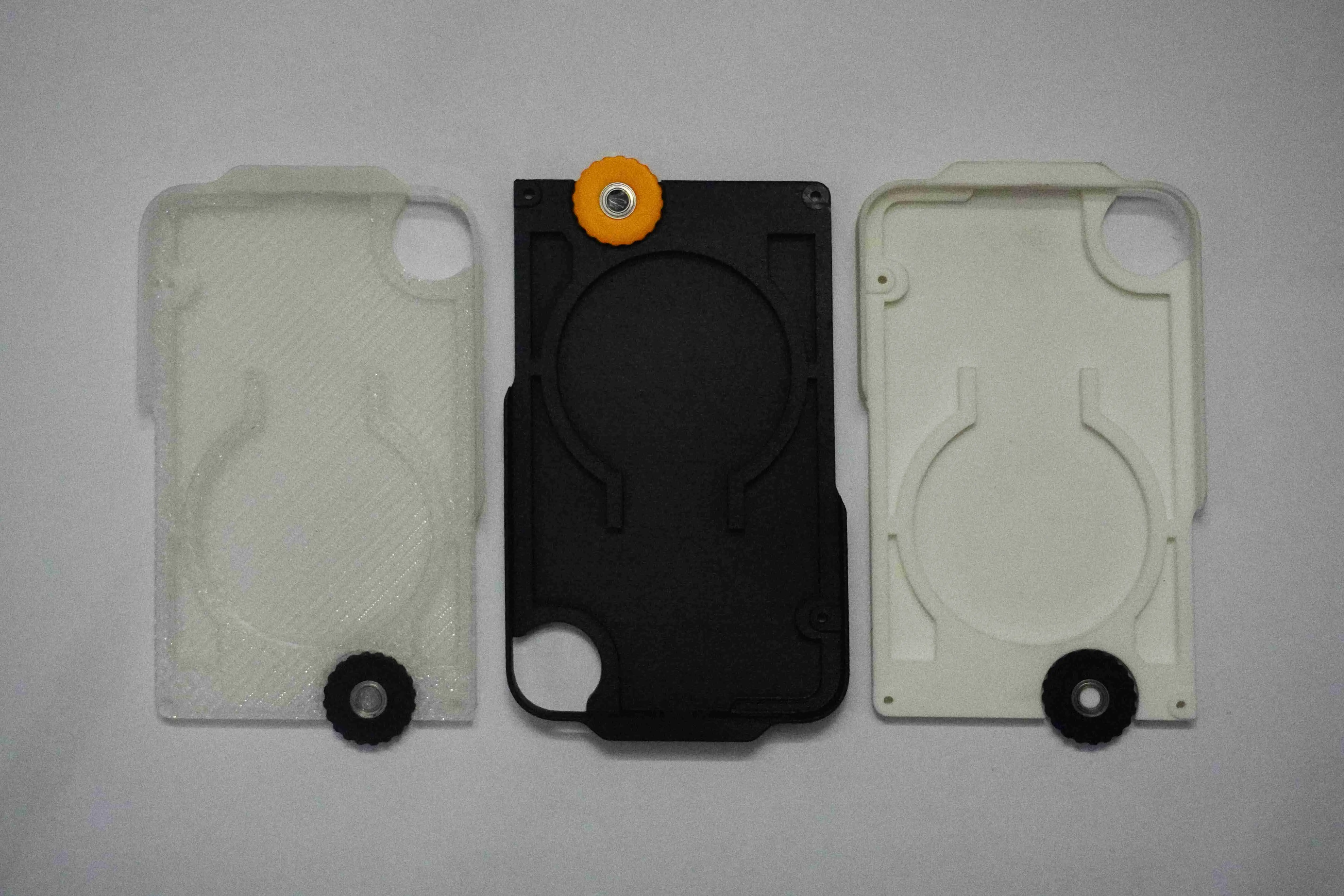
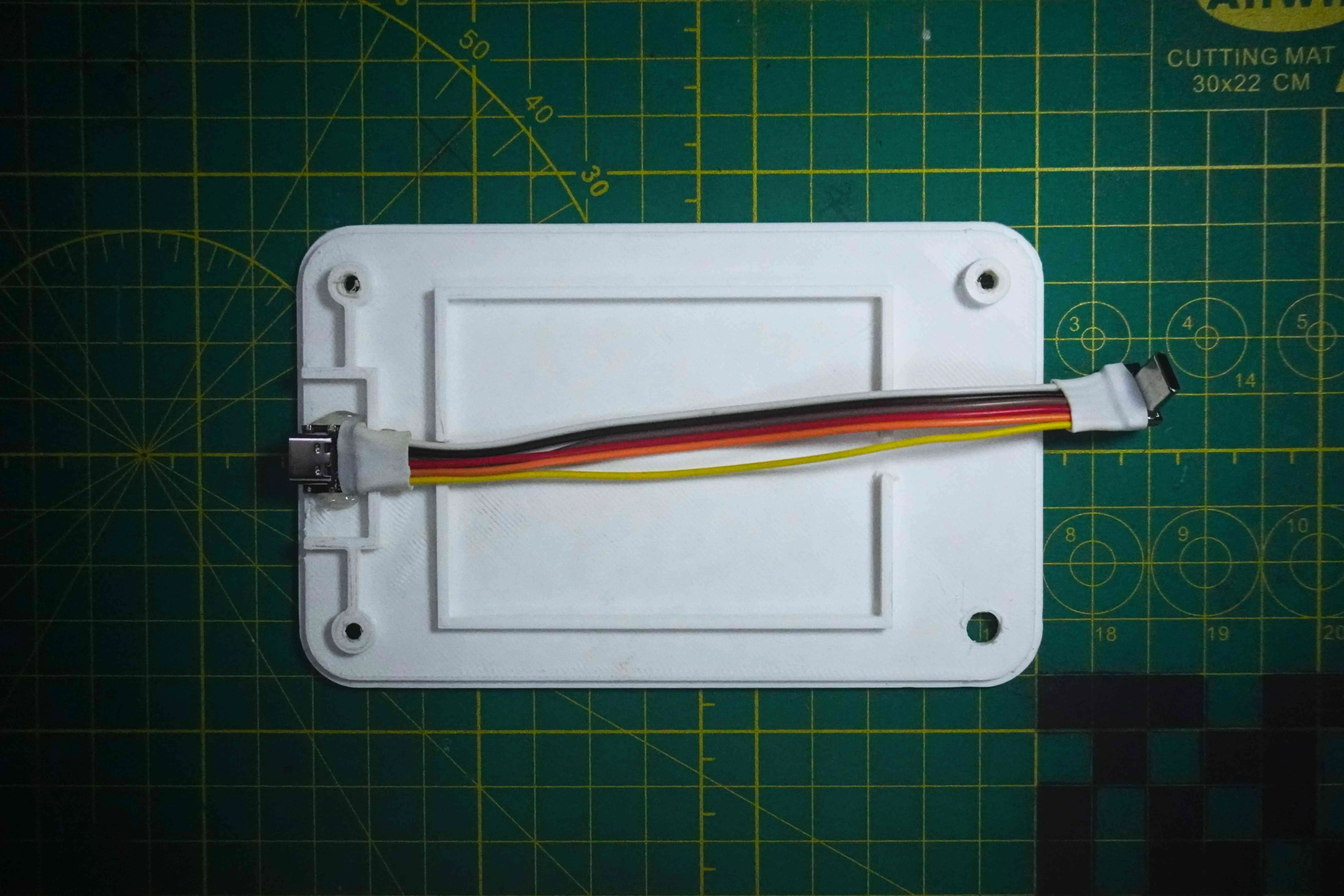
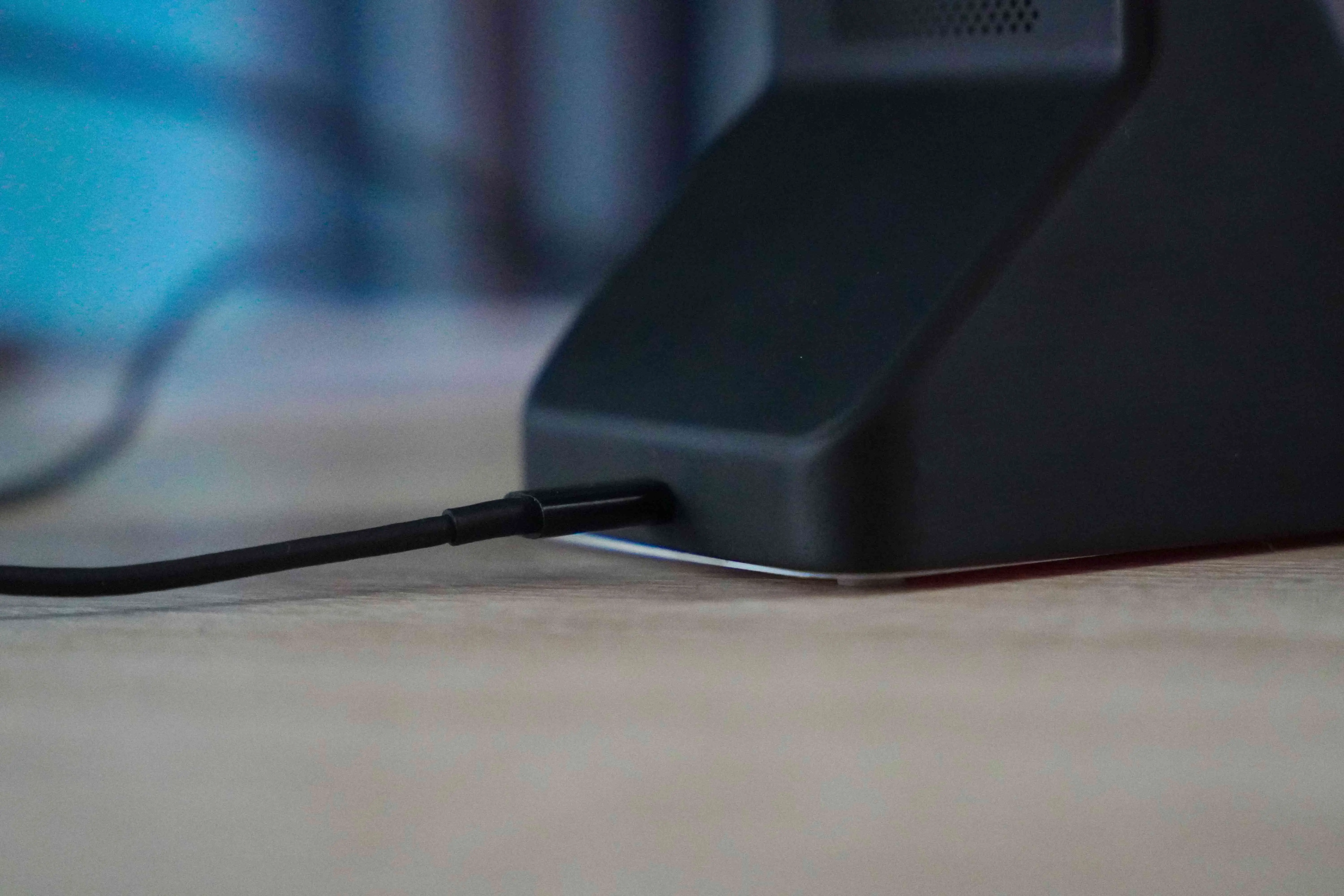
My original plan was ambitious: a custom case for my CMF Phone 1 with a built-in wireless charging receiver module that would connect seamlessly through the USB-C port. The idea was to split the USB-C connection—one path to the wireless charging coil and another to a secondary female USB-C port for connecting to other devices. I designed a case that would house both these parts and sent the dimensions to a friend for a custom PCB.
When everything arrived, I soon realized I had overlooked a critical detail: the PCB dimensions turned out to be too large to fit inside the case. Making the case bigger wasn’t an option since it was already as compact as I wanted it to be. On the other hand, if I made the PCBs smaller, there wouldn’t be enough room for the USB ports. So, my plans to split the connection fell apart.
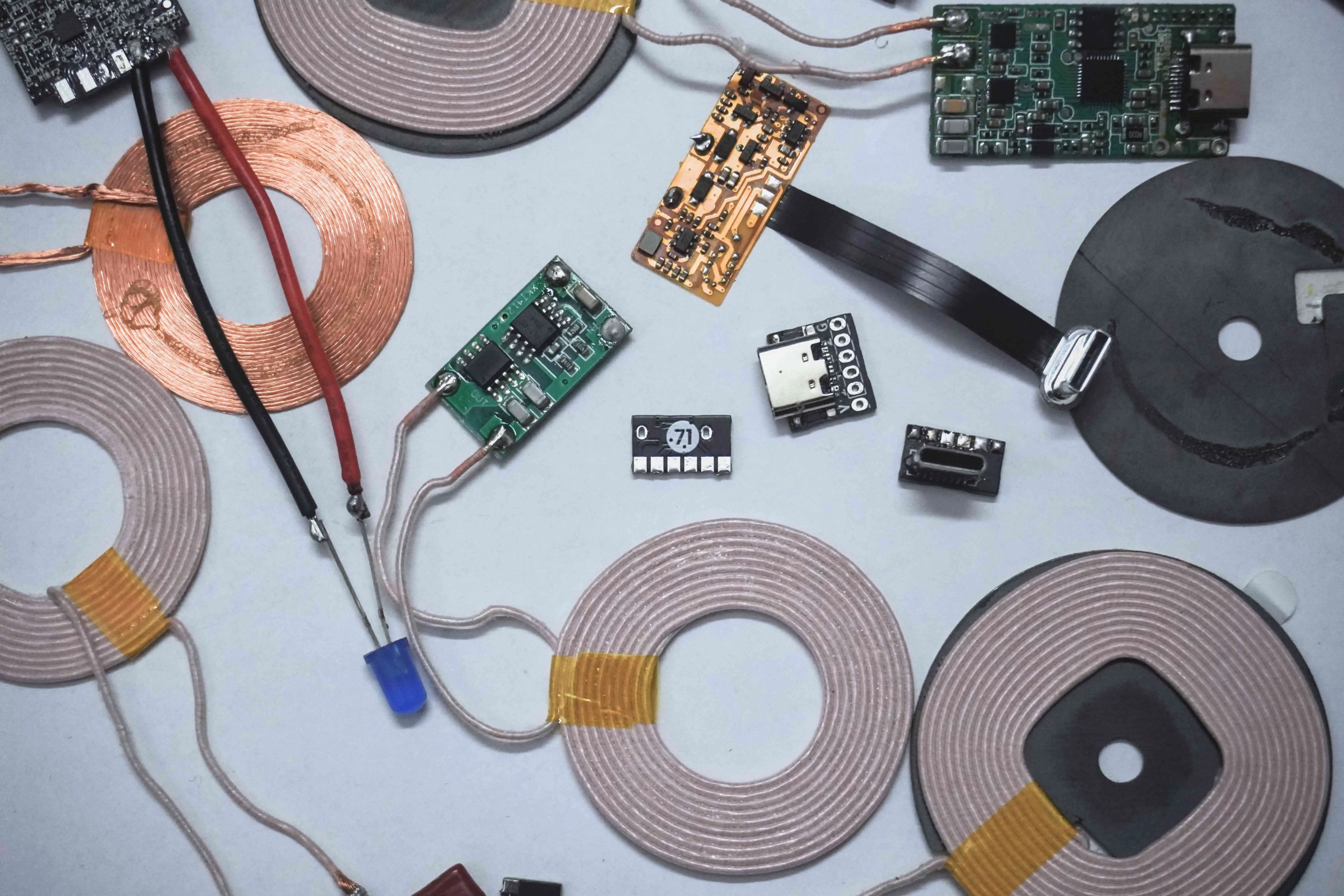
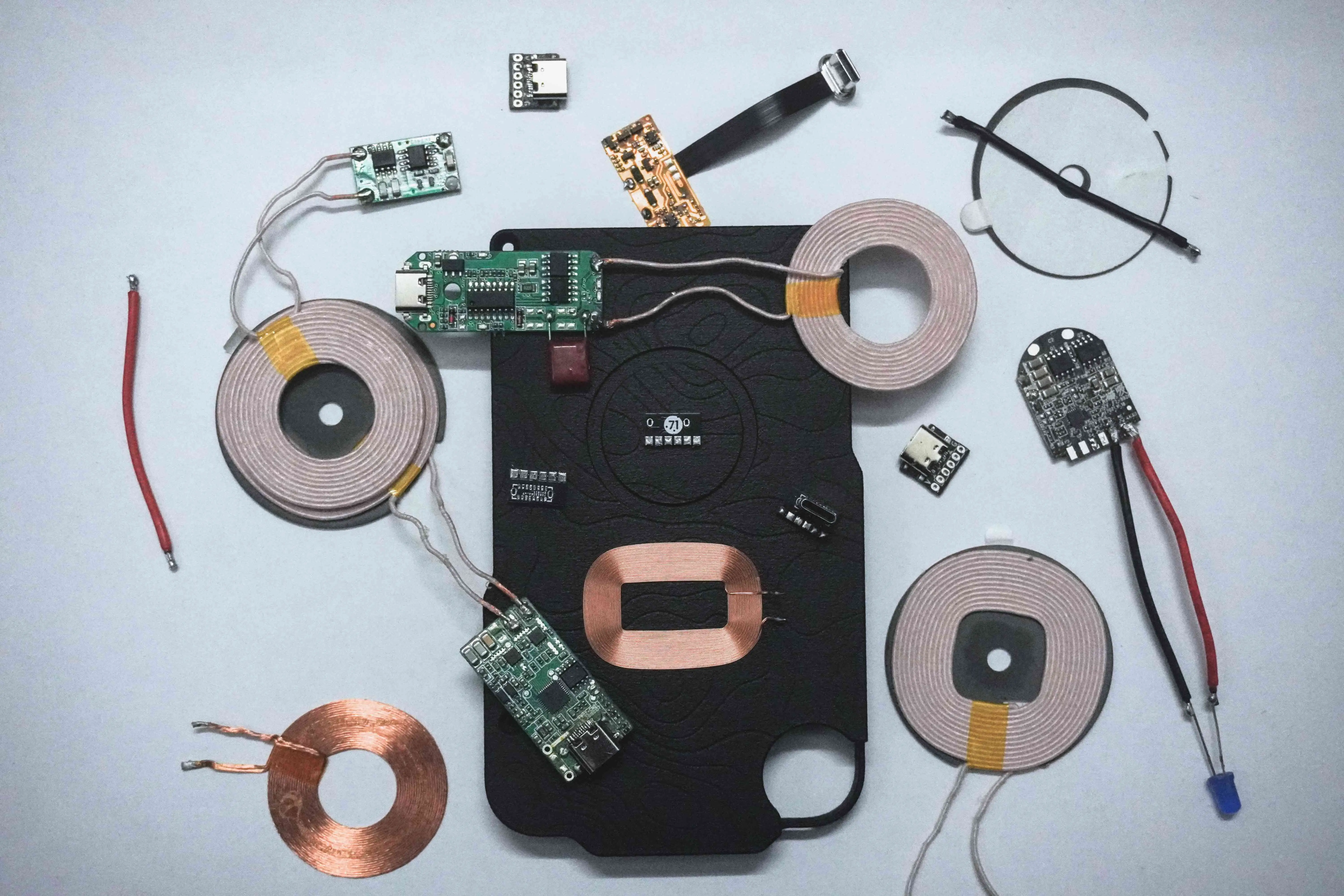
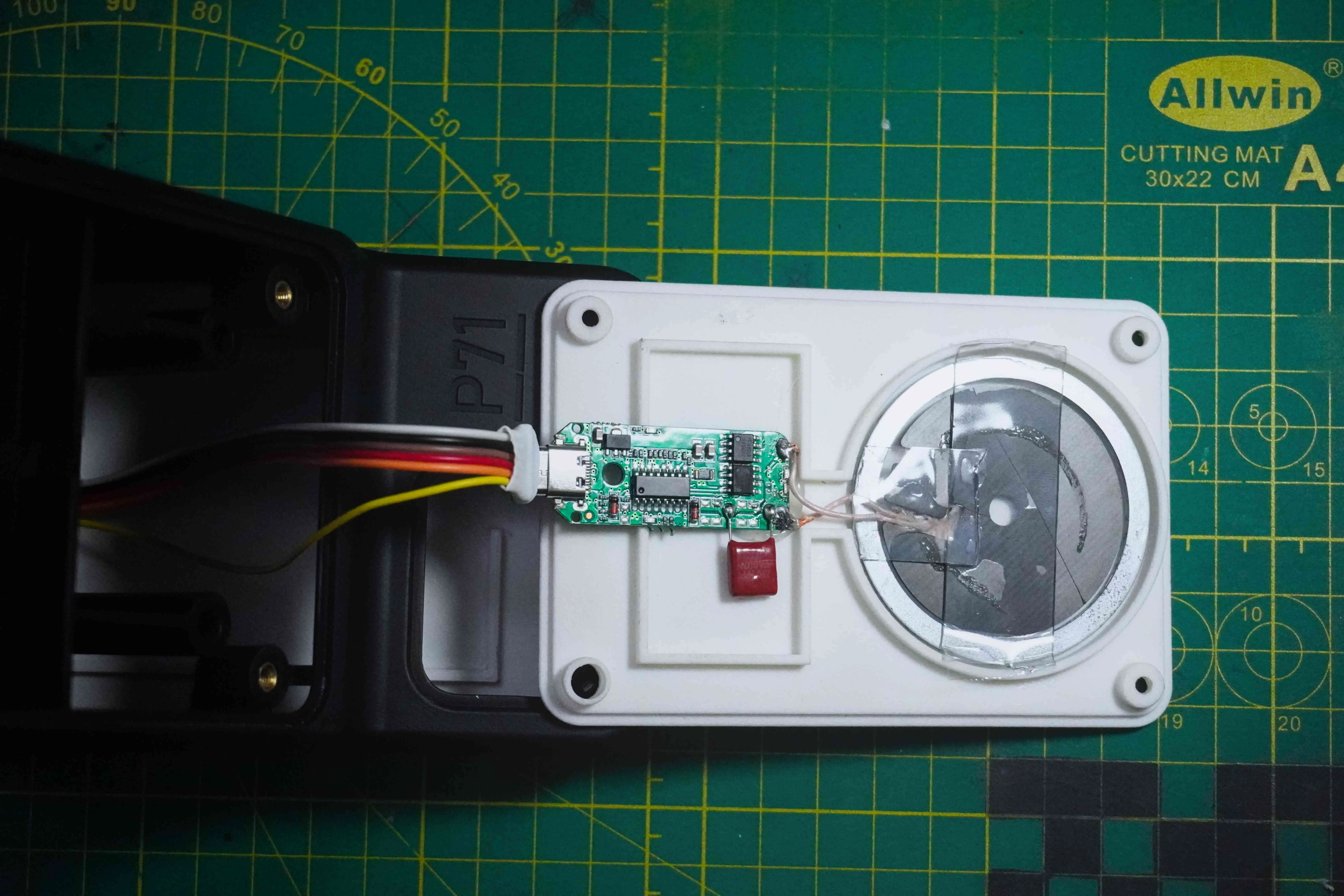
Determined to keep moving forward, I decided to test out a ready-made USB-C wireless charging flex circuit that I could attach to the phone. I ordered a couple of these modules, hoping they’d work, but they only charged the phone briefly before overheating and failing. With no way to diagnose the issue, I had to abandon the idea of wirelessly charging my new CMF Phone 1—for now.
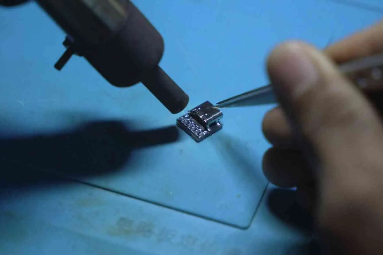

However, I didn’t want to waste the custom PCBs, so I repurposed them as the USB-C female to male connector for the dock, which at least salvaged part of my original plan. This setback marked a shift in focus. Instead of a custom case, I chose to focus on perfecting the dock, which I’ll use with my second phone that already supports wireless charging.
Refining the Dock: Integrating the MagSafe Magnets
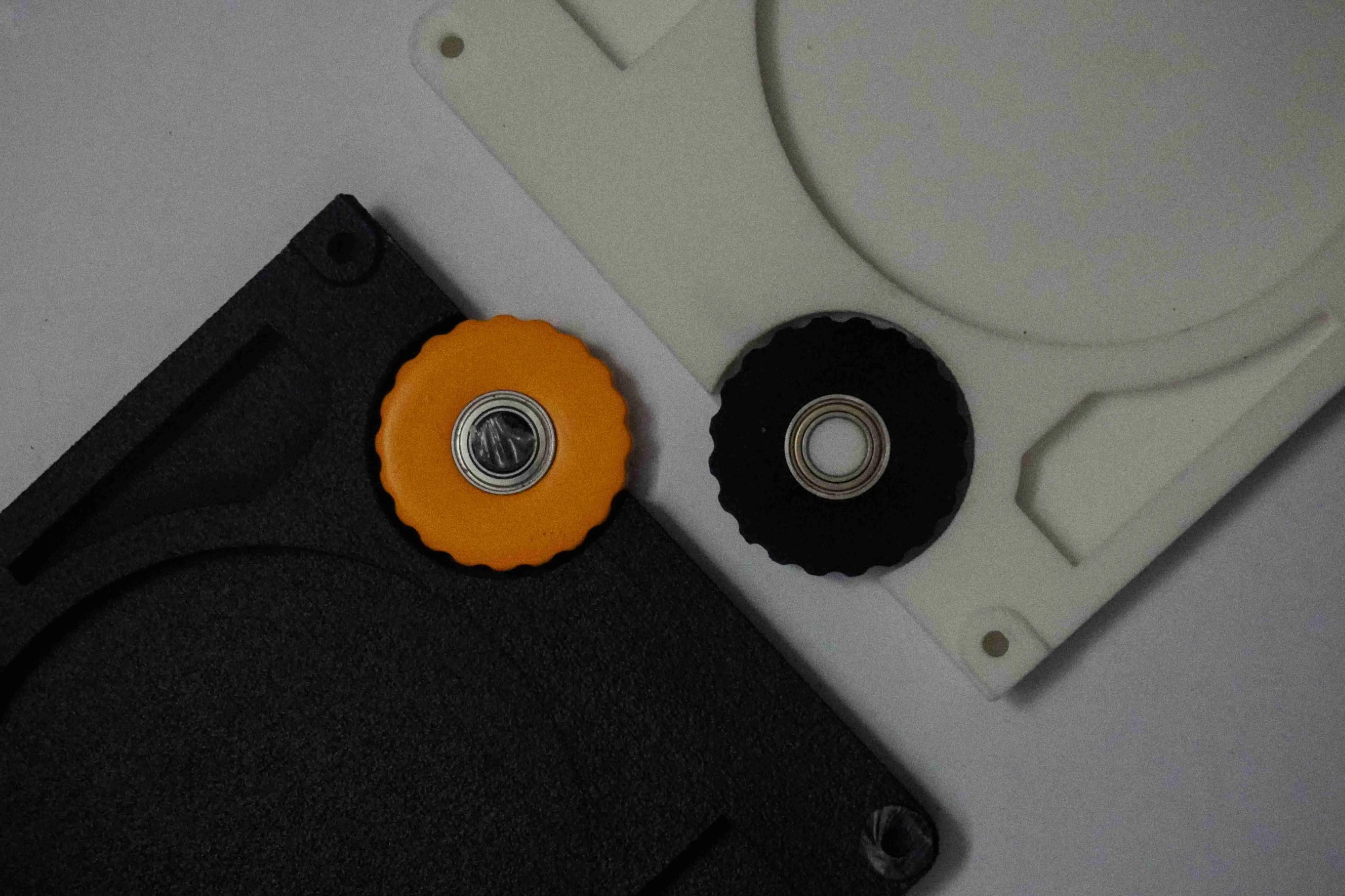
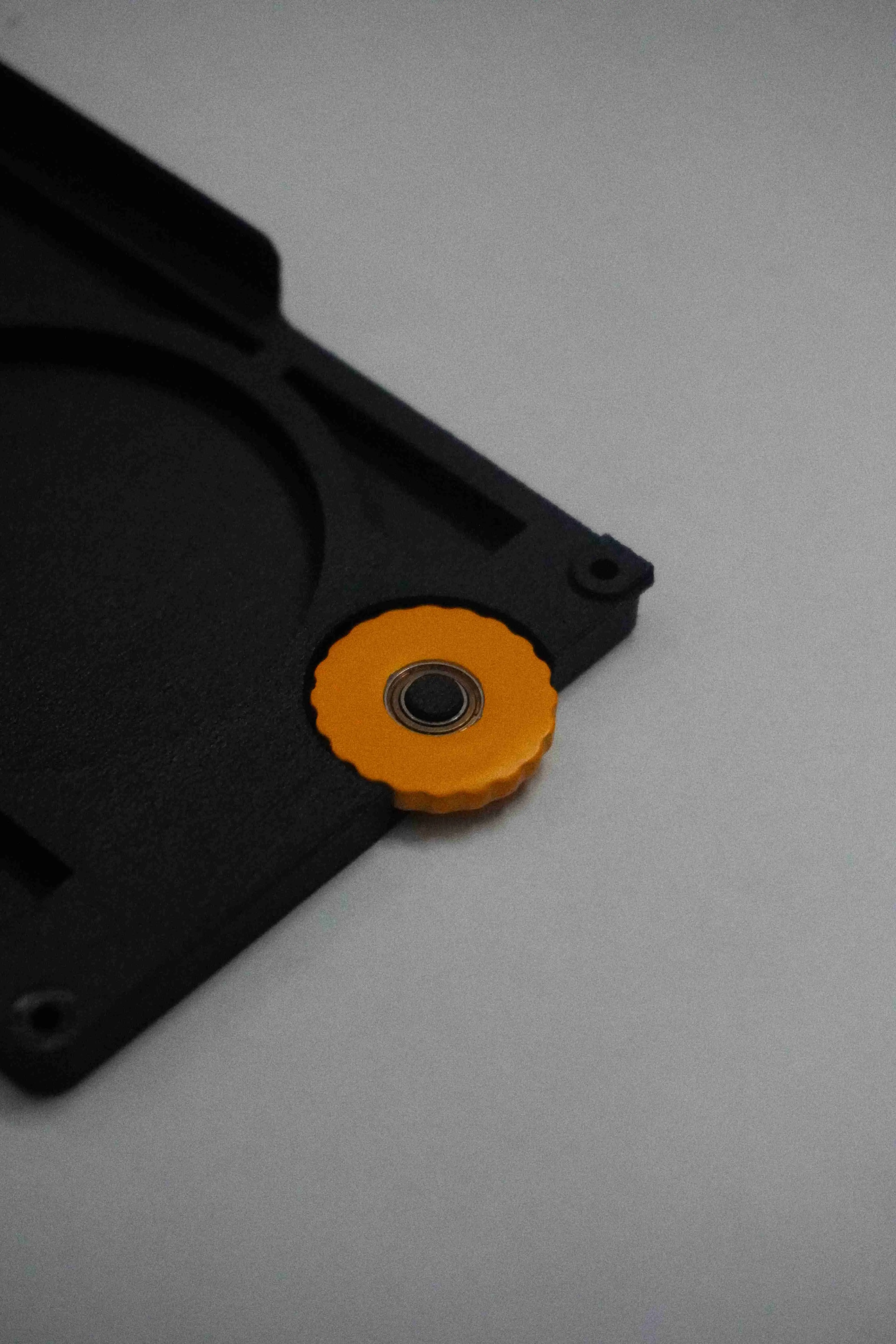
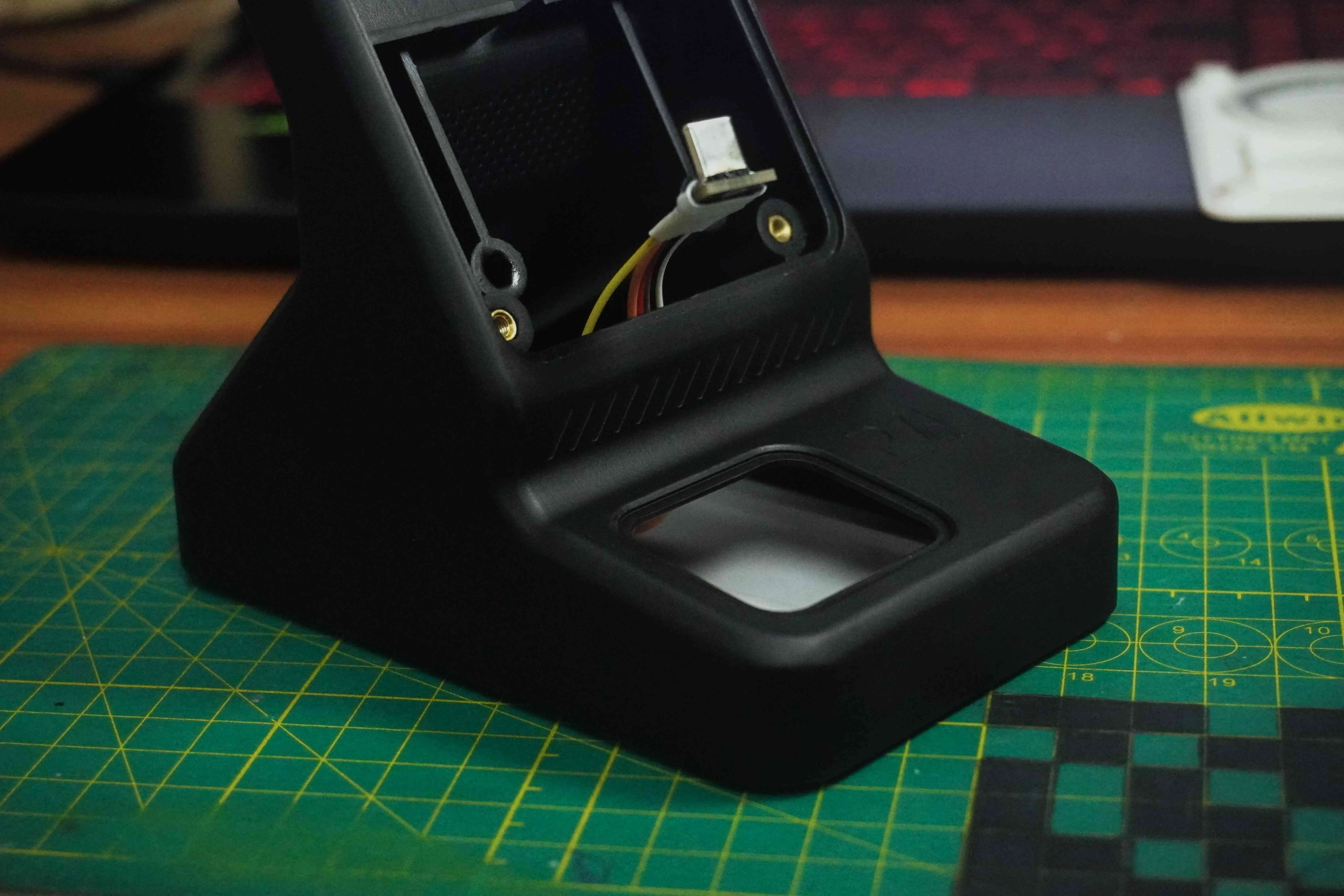
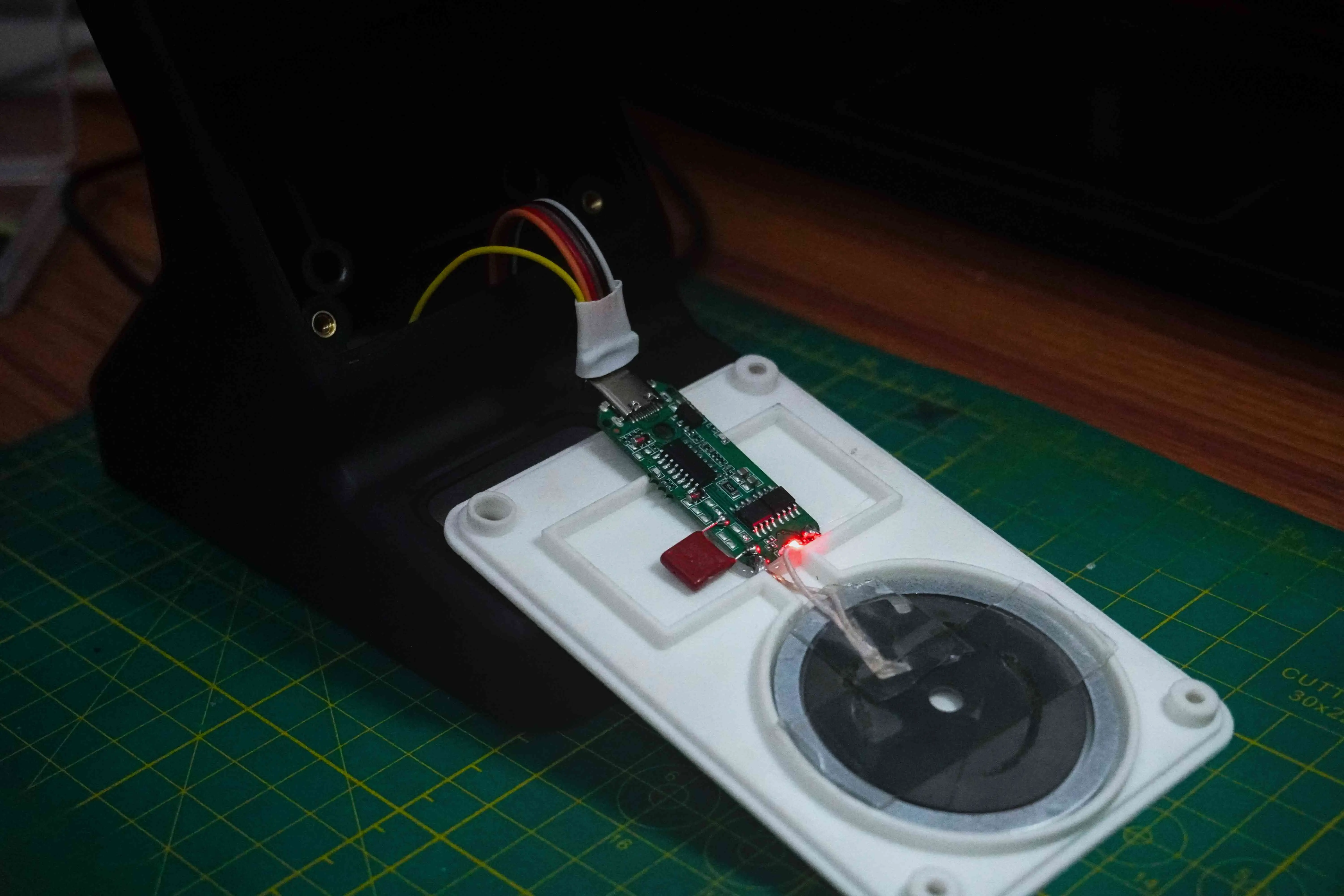
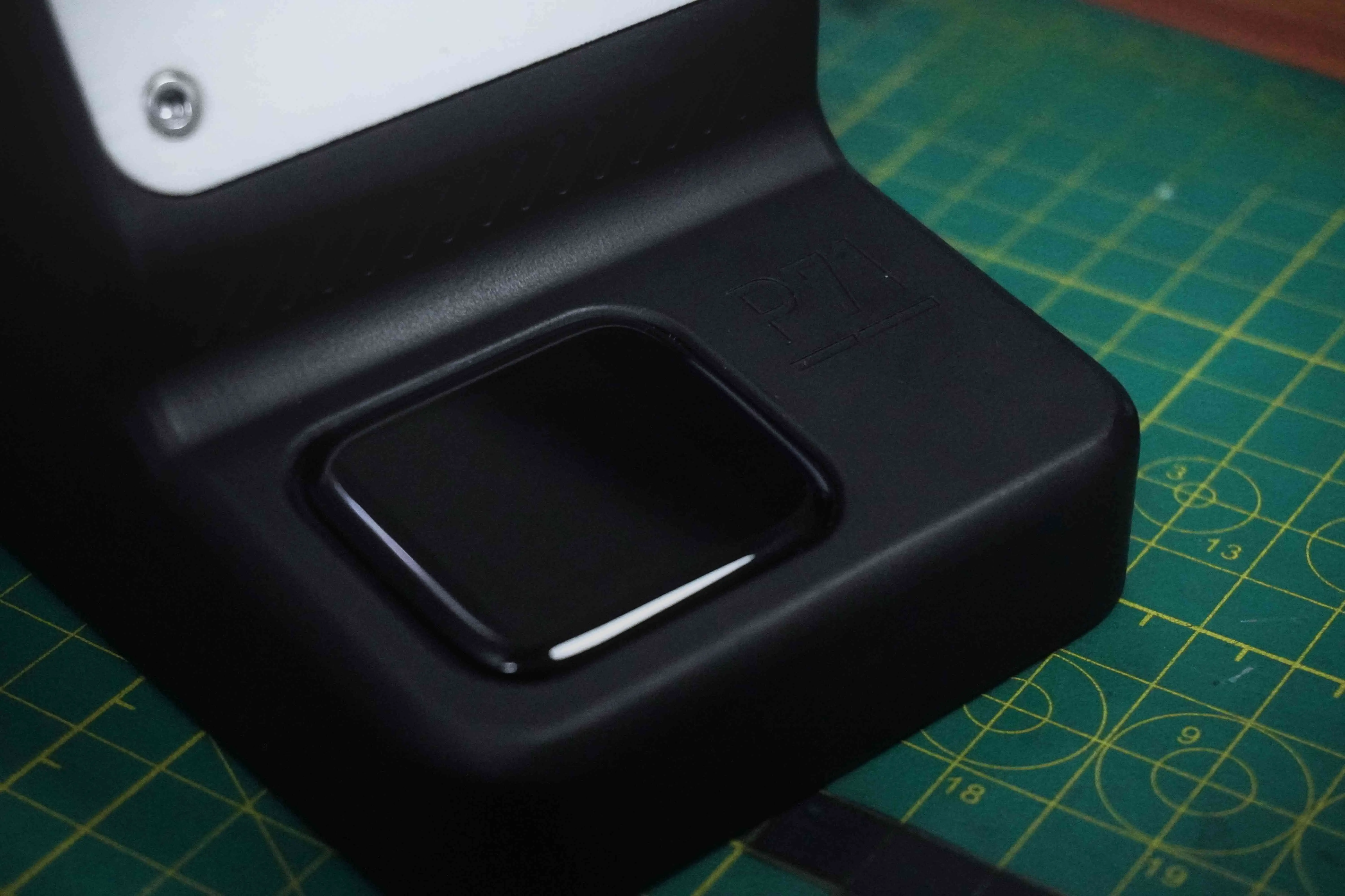
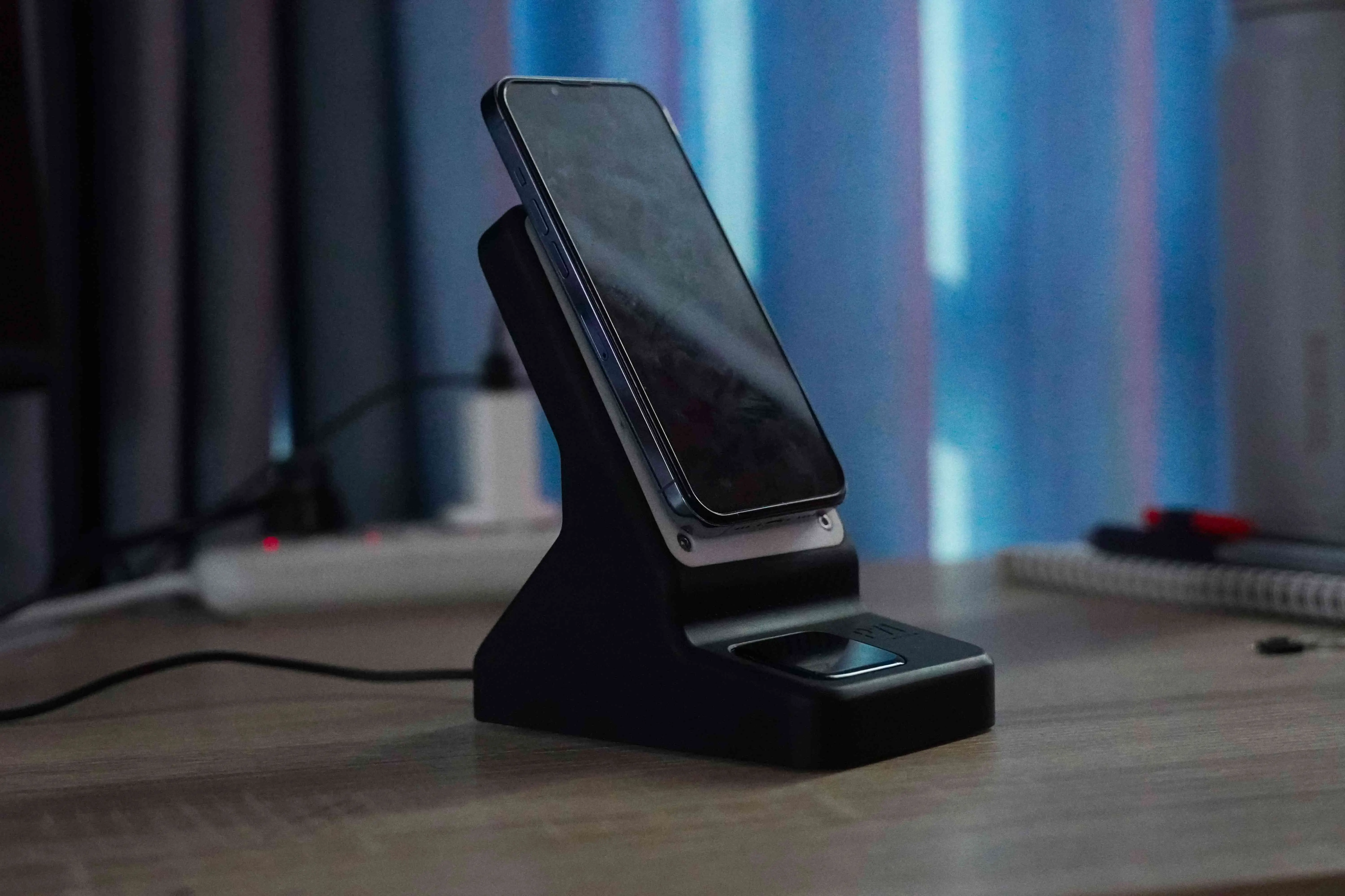
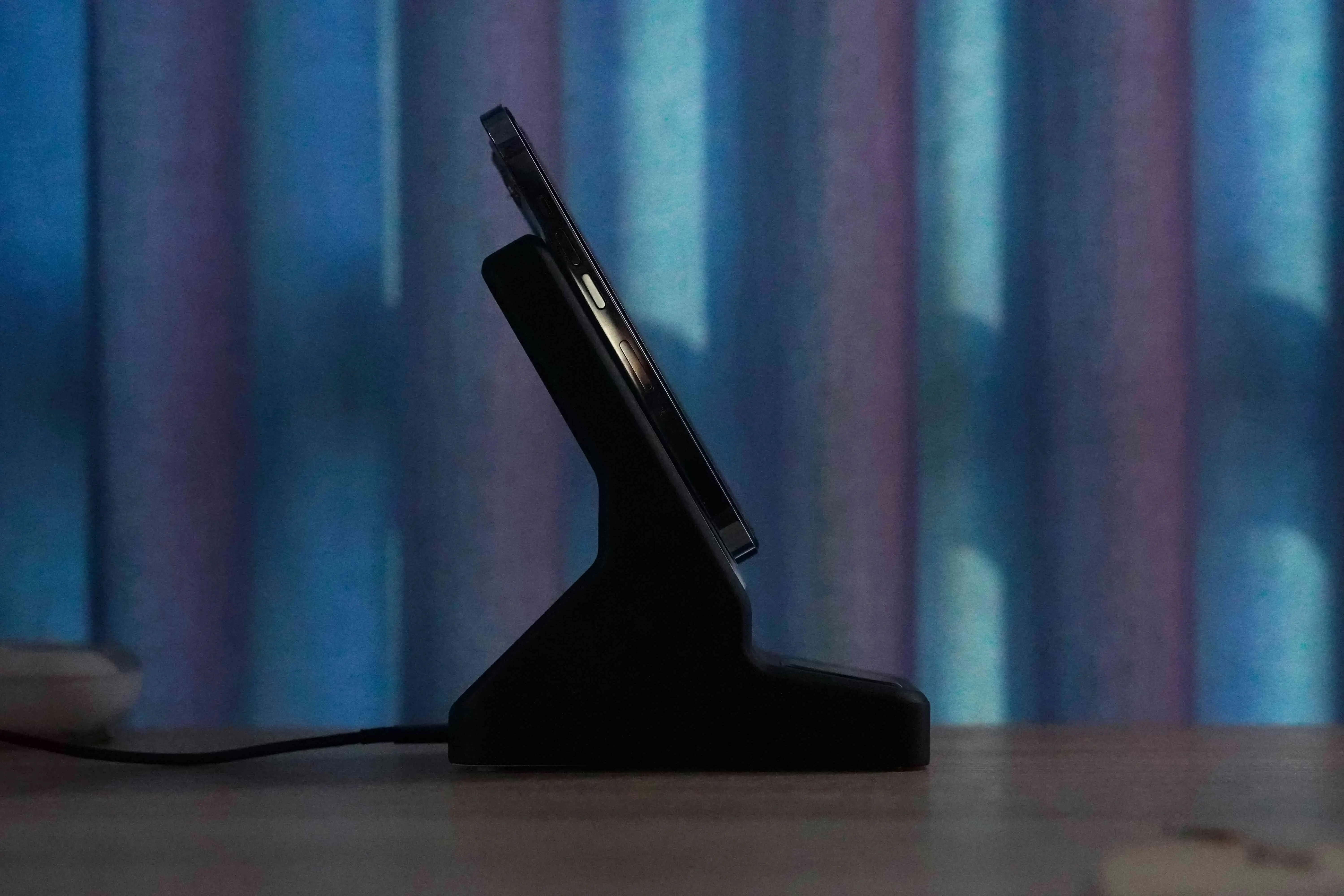
Integrating the MagSafe magnets was both straightforward and unexpectedly intricate. I wanted the magnets to hold the phone securely without disrupting the charging components or interfering with the circuitry. After several adjustments, I found the optimal positioning that allowed for stable alignment without compromising the charging function.
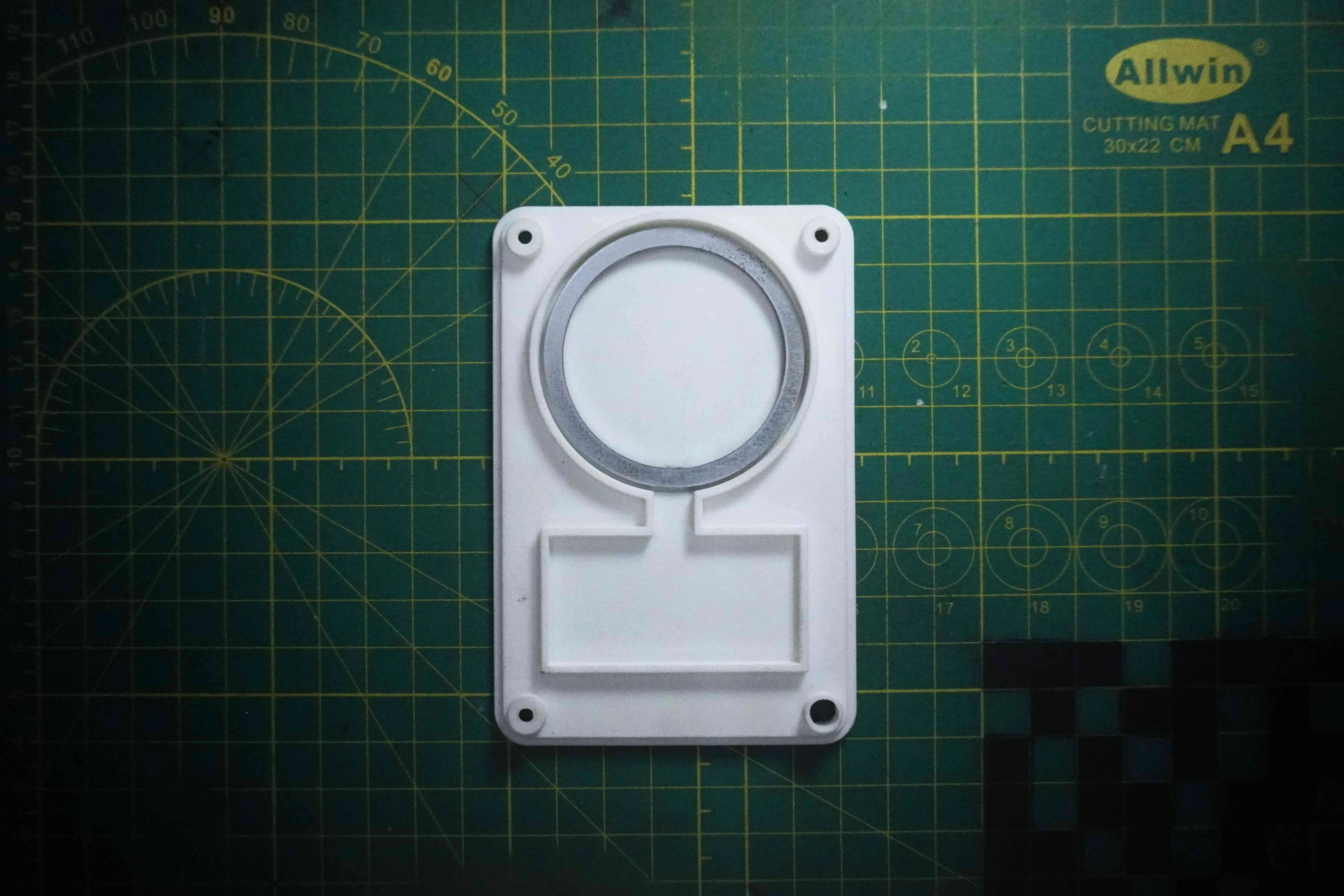
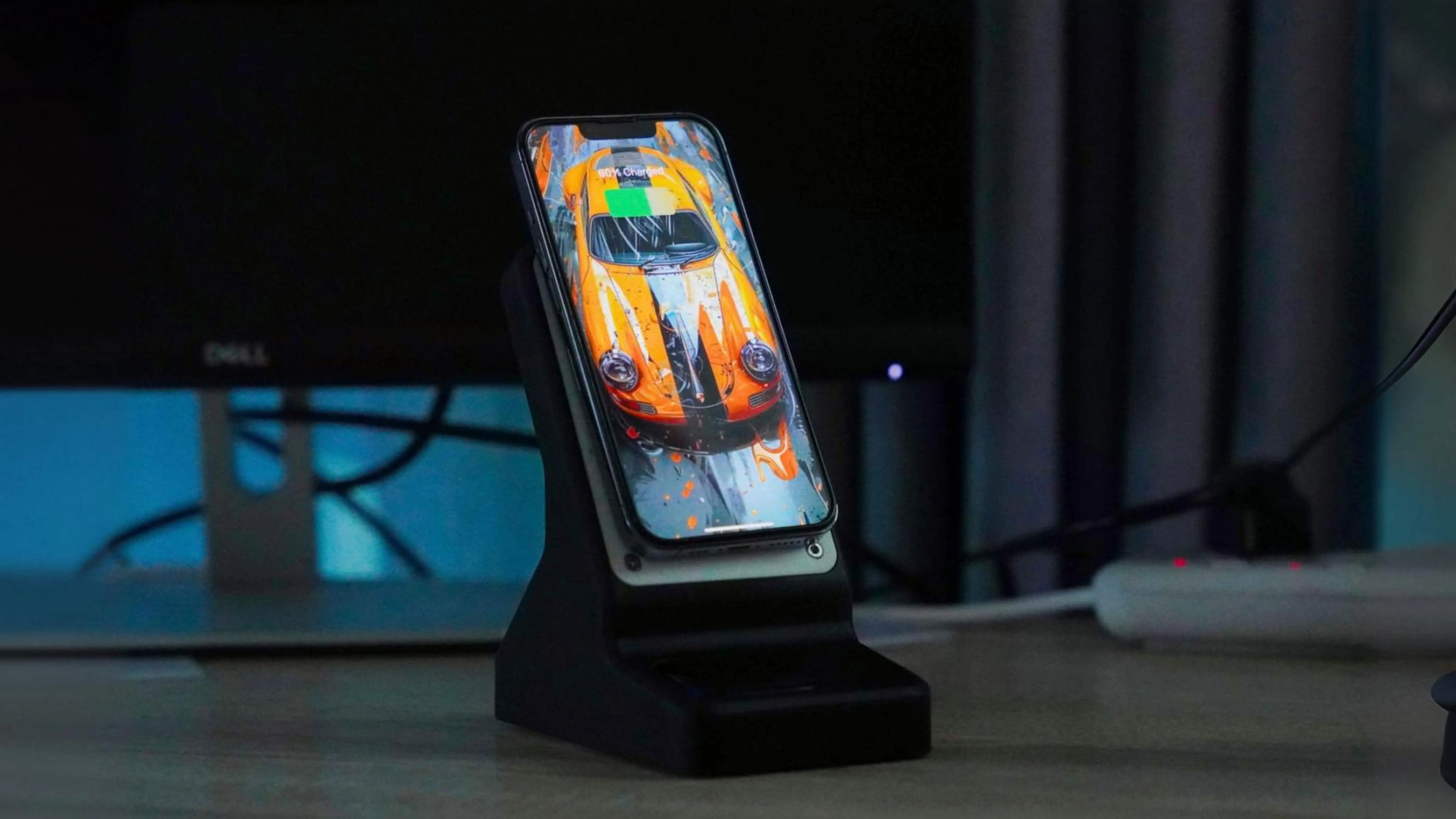
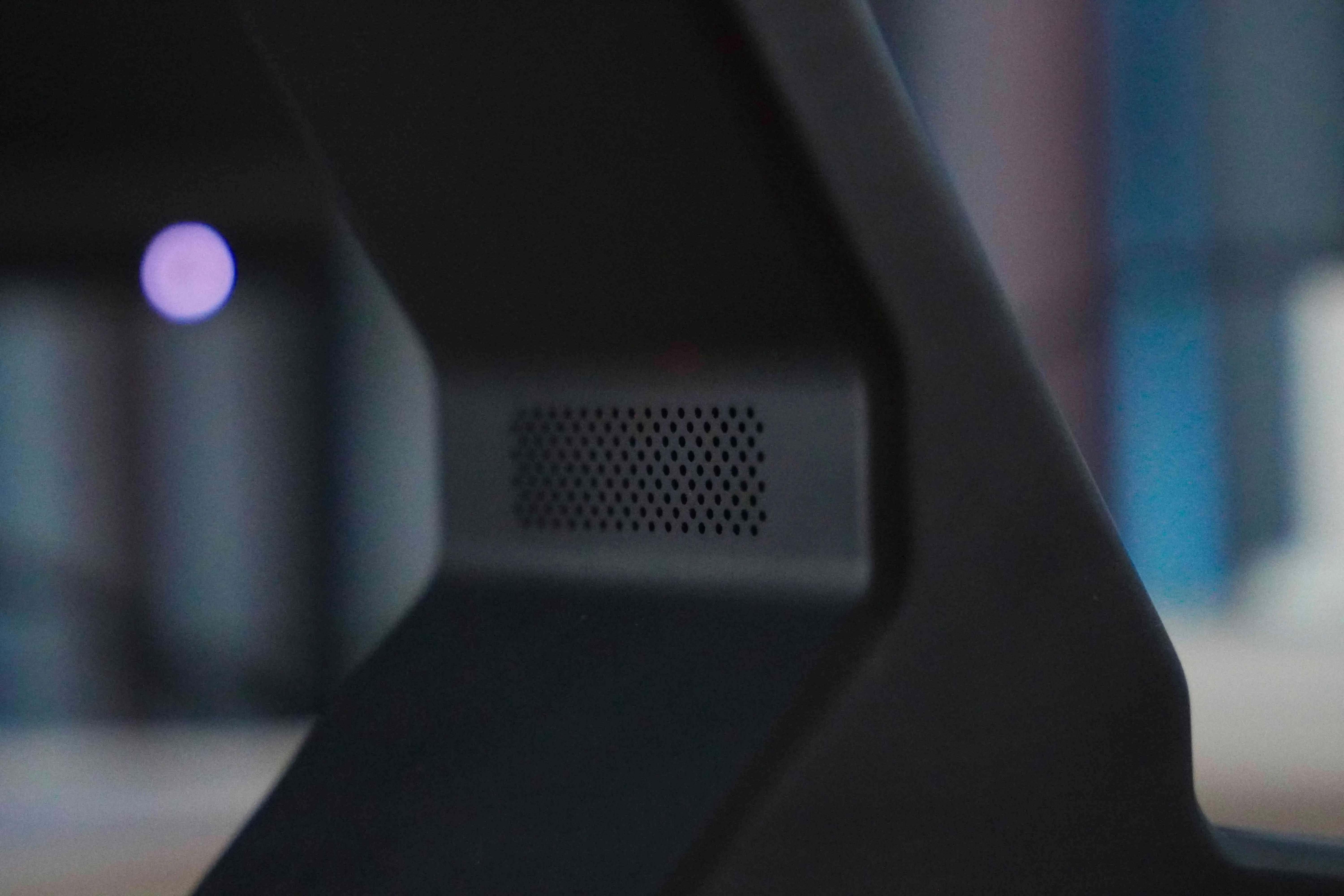
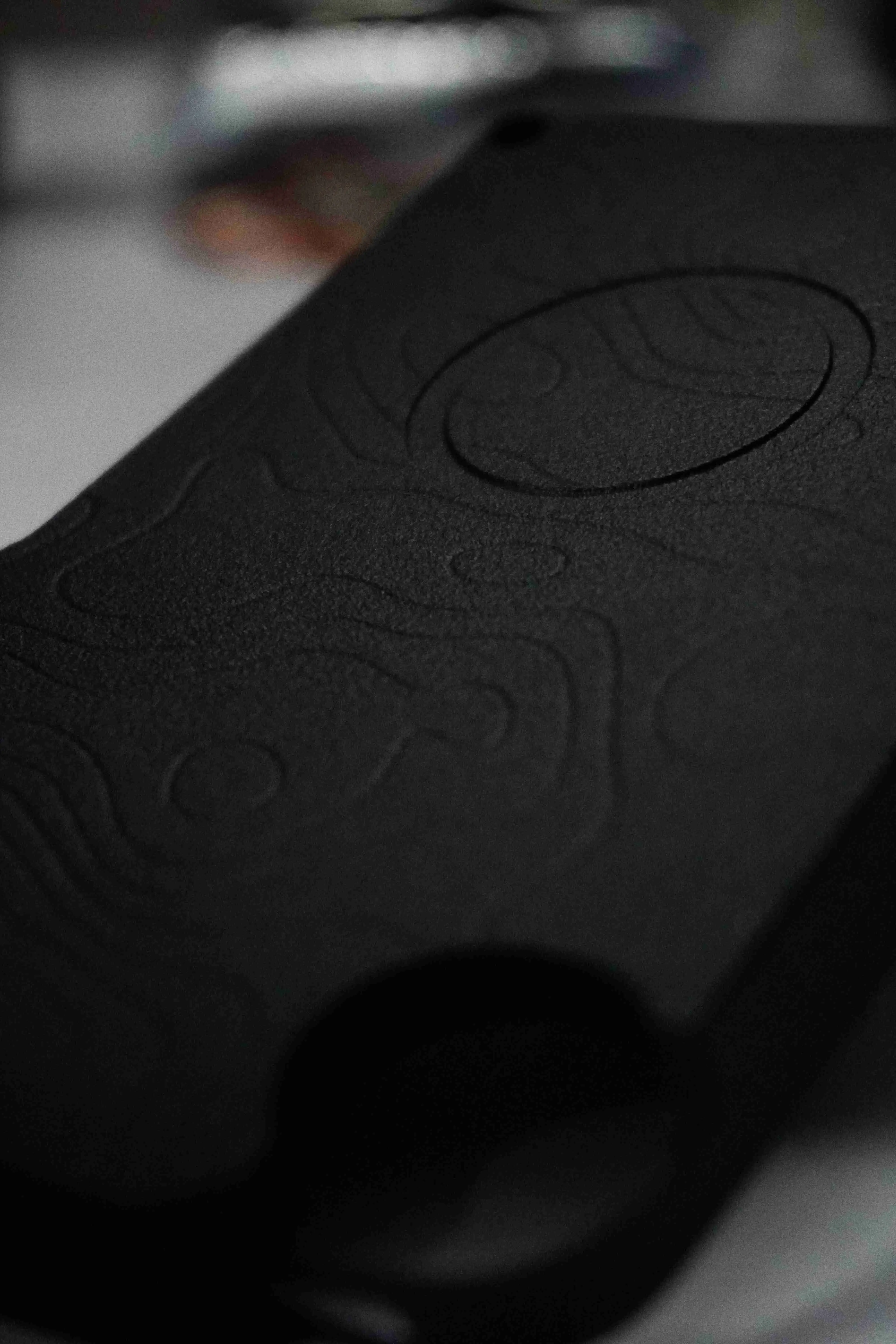
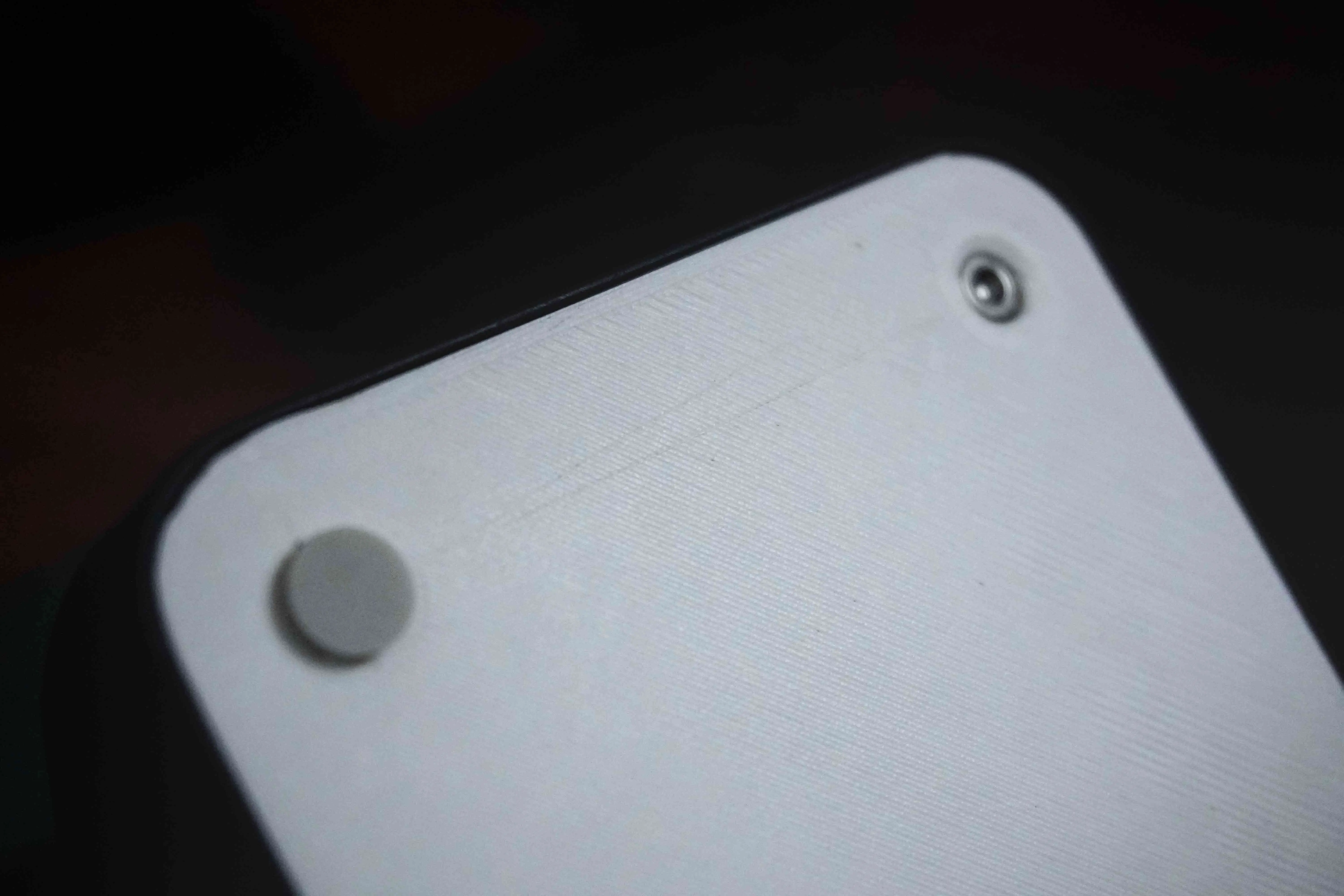
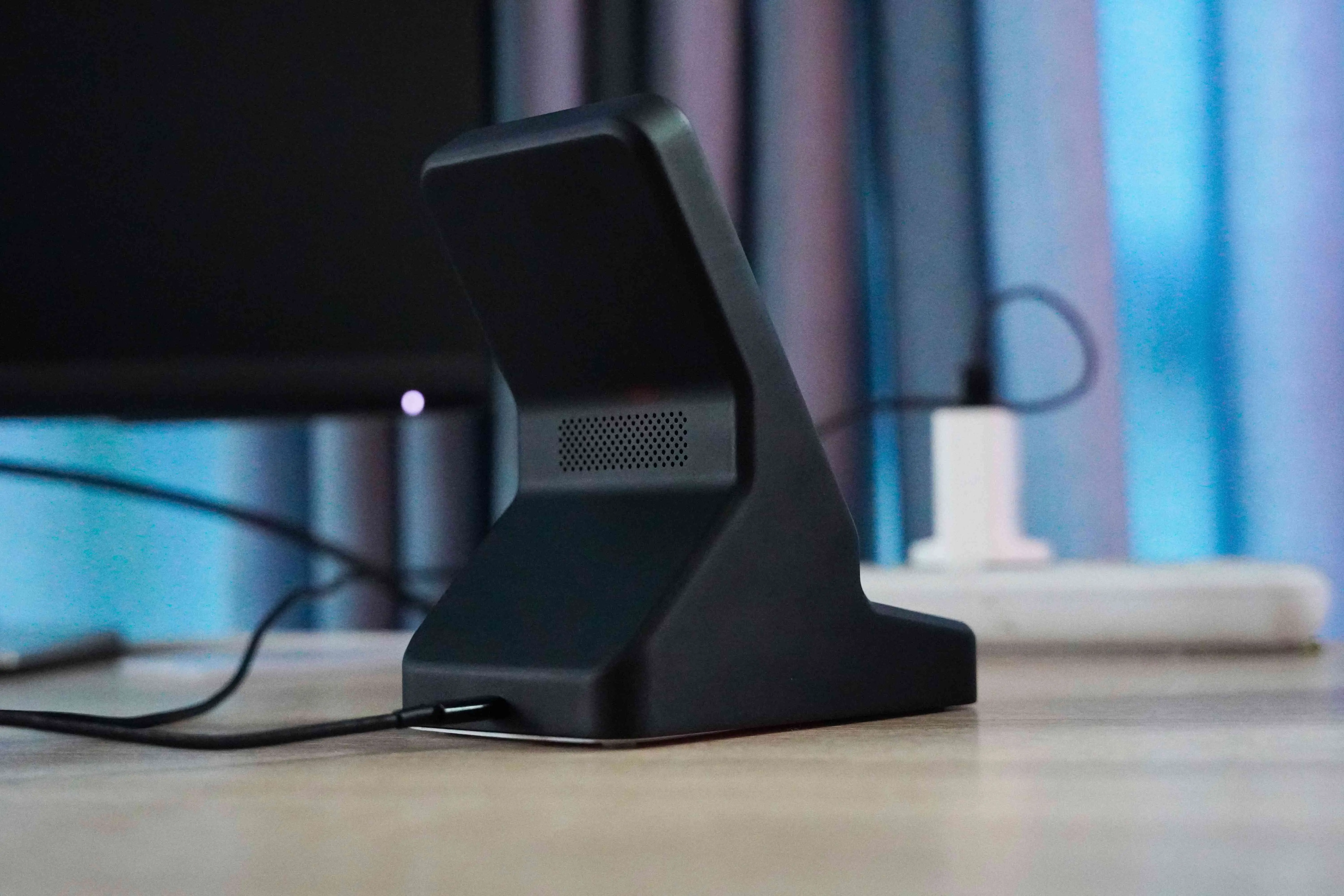
The dock’s transmitter PCB had a few LEDs that served as status indicators, lighting up in different patterns—pulsing when charging and steady when in “sleep mode.” I could use this signal to play something on the display that would reflect the charging status, adding a subtle visual effect to the dock. While I’m not ready to implement the display functionality just yet, I incorporated space for it in the design. For now, I’ll install a dummy display to get a sense of the final aesthetic. Additionally, I added some weights to the base for stability, rubber feet for extra grip, and exposed screws on the dock face to complement the CMF Phone’s industrial style – which will always remind me where this project started from.
Bringing It All Together: Final Assembly
After a lot of testing, rethinking, and adapting, I finally reached the point of assembly. The dock came together as I had envisioned—a blend of form and function and leaves room for future additions, like the secondary display. It’s satisfying to see an idea come to life, transforming from rough sketches and cardboard prototypes into a product.
Lessons Learned and Future Plans
This project reinforced a core lesson: flexibility is key. Although I had to let go of the initial plan for a custom case, shifting my focus allowed me to create a refined, standalone dock that I’m genuinely proud of. It’s a product that not only works well but also feels right—reflecting both the phone’s aesthetics and my own vision as a maker.
Moving forward, I already have ideas for improvements. I’m considering adding more customization options for the display, experimenting with new materials, and even revisiting the wireless charging case idea when I find a better solution. For now, though, I’m content with the dock as it is—a testament to the power of iteration, patience, and a bit of maker’s resilience.
