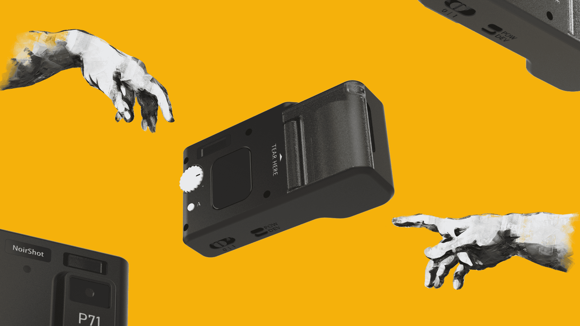
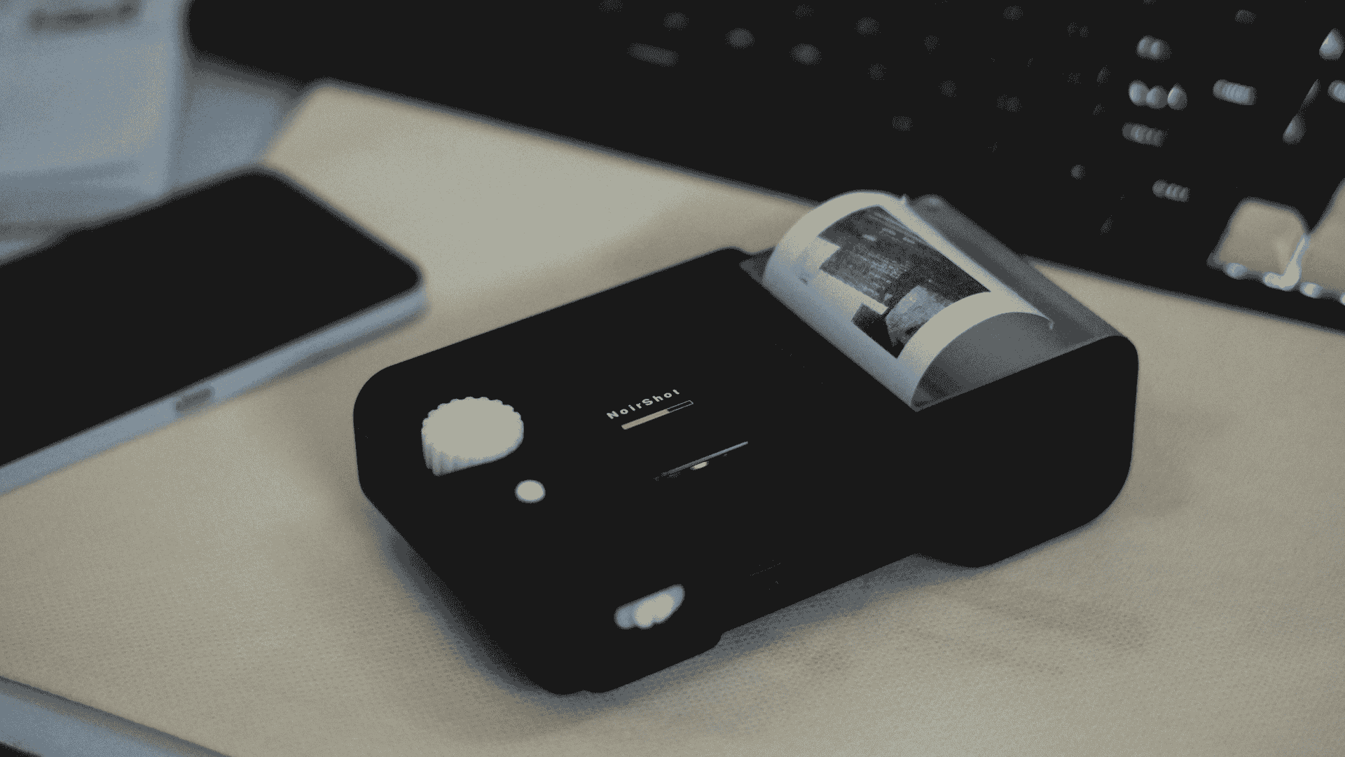
There’s something undeniably satisfying about hearing a tiny thermal printer whirr to life and slowly spit out a black-and-white image on receipt paper. NoirShot came from chasing that feeling — and from a desire to build something that merged electronics, mechanical design, and a bit of nostalgia into a working object.
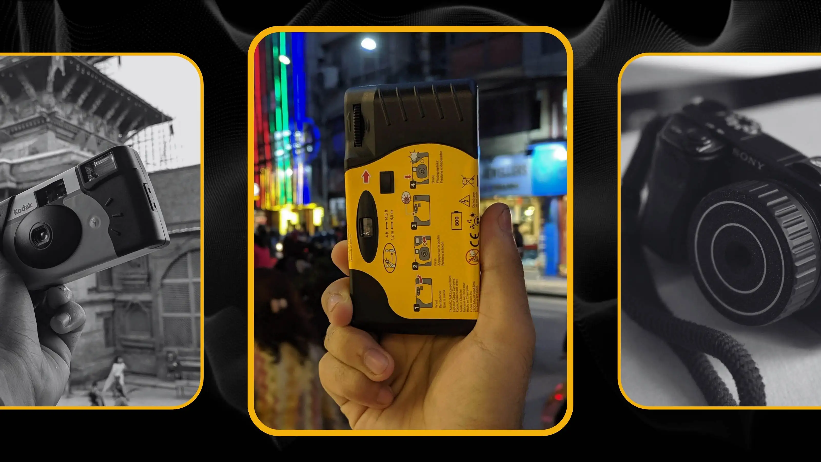
This isn’t my first attempt at capturing that analog charm. I’d previously hacked a Kodak Funsaver lens onto a Sony A6400 in a 3D-printed shell I called Dispolens. NoirShot takes a different route — ditching optics entirely and going digital: thermal printing, instant output, and a DIY approach to everything from the shell to the PCB.
This writeup documents how I built it. The plastics, the circuits, the assembly, the problems — all of it. I’ve also put together a build video over on my YouTube channel for those who prefer a visual walkthrough.
Why Build Another Instant Camera?
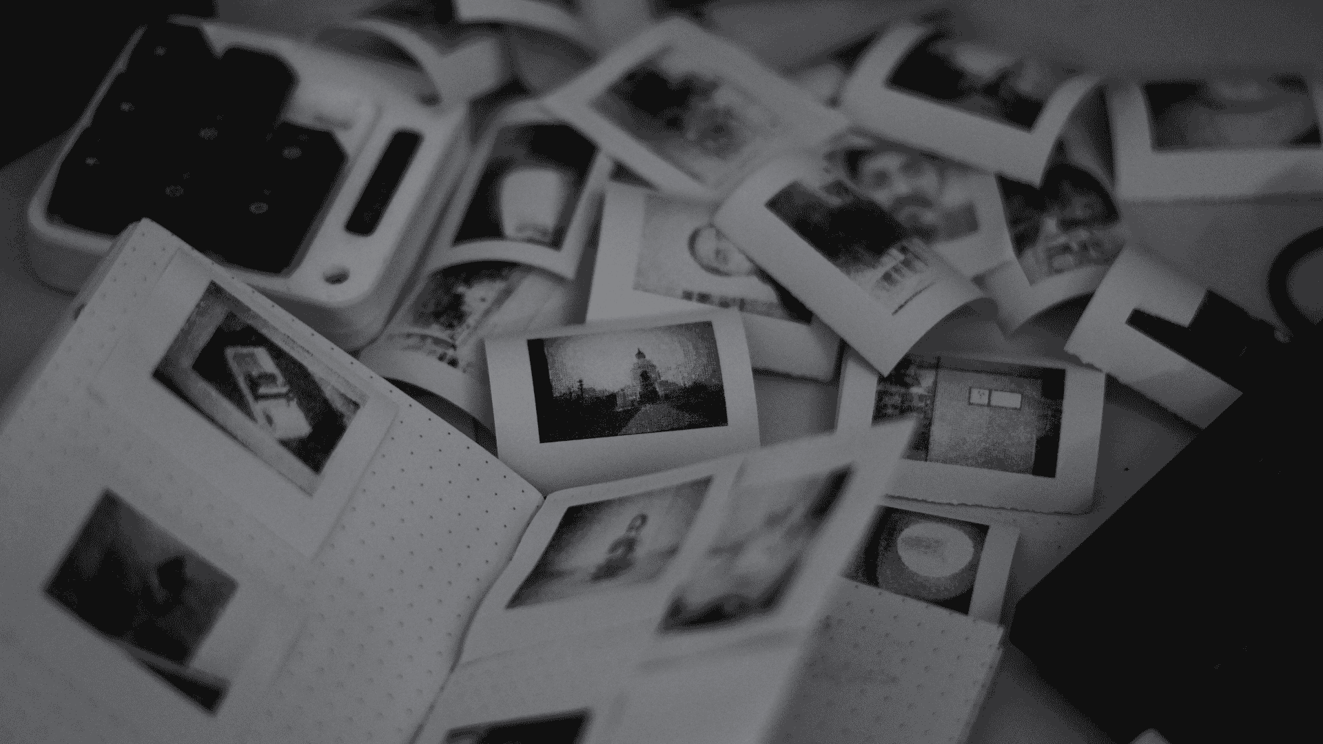
The seed for NoirShot was simple: What if I could make a point-and-shoot-style instant camera, but one that used a thermal printer instead of film? Not for photorealistic prints — I wasn’t aiming for Instax quality. I wanted low-fi, grainy, high-contrast charm on cheap paper. Something you’d use to capture little moments with no pressure.
More importantly, I wanted to actually design the product — not just shove modules in a lunchbox. That meant thinking about the case, the mechanics, the internal layout, how the roll of paper feeds, how the buttons feel. The whole product experience.
Core Components
Here’s what makes up the NoirShot camera:
- CH32V203C8T6 by WCH: A RISC-V microcontroller (64 MHz, 64 KB Flash, 20 KB SRAM) acting as an intermediary processor. It receives image data from the ESP32-CAM, handles minimal processing, and streams it to the thermal printer. It also drives the display and handles all user input via buttons.
- ESP32-CAM module: Captures images via its onboard camera and sends them over serial to the CH32V203.
- Thermal printer module (58mm): Standard thermal printer, typically used in receipt printing applications.
- 1.69” IPS TFT display: Provides a minimal user interface — showing capture status, print confirmation prompts, and system states.
- LiPo battery: Rechargeable power source with USB-C charging and onboard protection circuitry.
- Custom intermediate PCB: Interfaces between the ESP32-CAM, CH32V203, and thermal printer. Also routes signals for buttons and display, consolidating the system into a compact, reliable layout.
On the mechanical side:
- Housed in a 3D-printed body designed for clean assembly and a compact, ergonomic grip.
- Magnetic paper cover for easy paper roll changes.
- Designed for efficient printing with minimal supports and a clean, functional look.
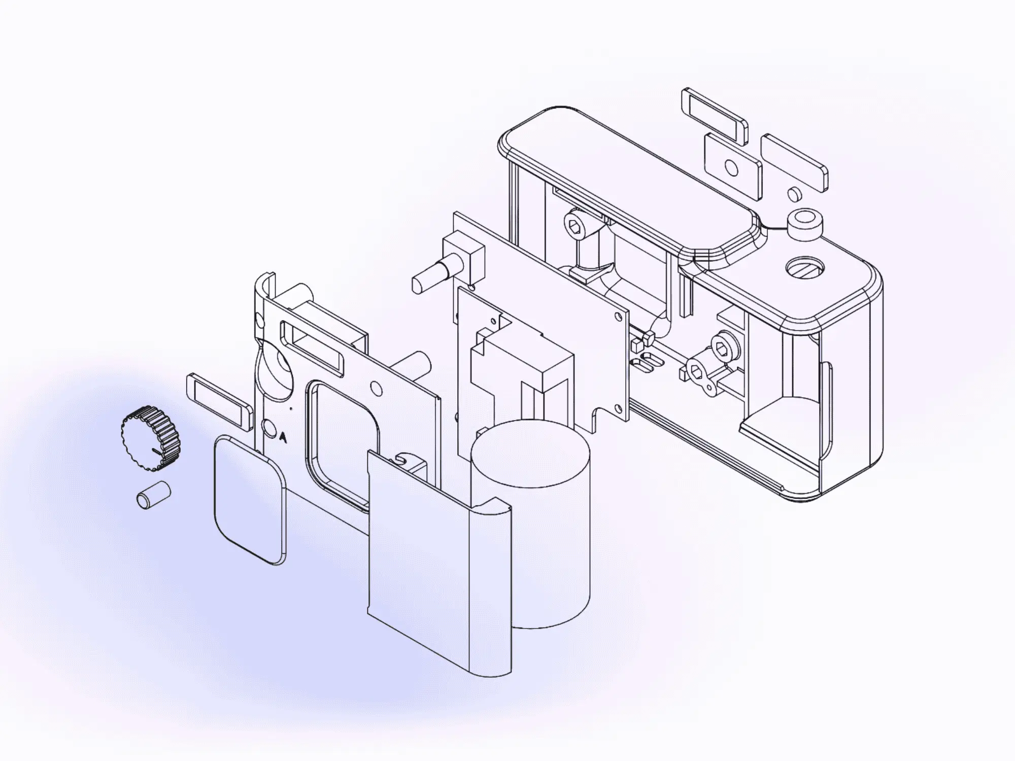
Designing the Enclosure
All mechanical design was done in SOLIDWORKS, starting from a top-down layout of the key components. The final form balances the camera on the left, the printer in the center, and the paper roll neatly housed in a hollow handgrip for better ergonomics and internal efficiency — inspired by classic Polaroid proportions.
The thermal printer’s geometry dictated much of the layout — especially feed direction, roll placement, and clearance for the heated print head and tension system. Instead of repeated prototyping, I relied on my background in consumer electronics to visualize and validate most of the assembly in CAD, printing just a single cross-sectional test to verify internal fits.
The interface is intentionally minimal: a clickable rotary knob, a multipurpose button, and a small display for clear user feedback.
Circuitry & Rabin’s Intermediate PCB
Now here’s where it gets interesting.
Instead of wiring the ESP32 directly to the thermal printer, my friend Rabin (who’s way better at embedded stuff than I am) designed an intermediate PCB. This board acts as a middleman between the ESP32-CAM and the printer, connecting them over a serial interface.
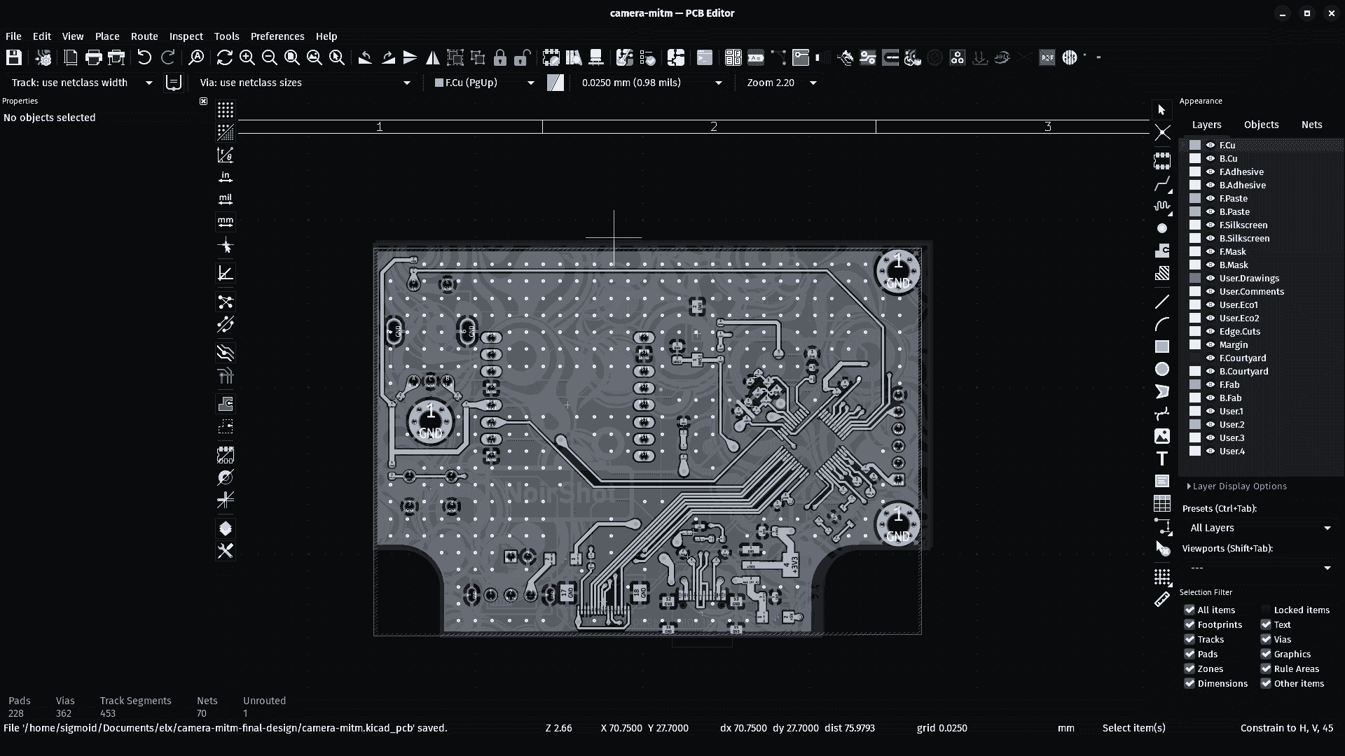
But it doesn’t just bridge data. Rabin also added CH32V203C8T6 MCU, creating a robust and modular link between the ESP32-CAM and the thermal printer that handles:
- Printer protocol, feed timing, and status monitoring interfacing with the thermal printer module
- Button scanning and debouncing logic
- Driving the UI display
- Handling USB-C power management and voltage regulation
- Enhanced System Integrity by offloading power-hungry and timing-critical tasks from the ESP32, we avoid brownouts, jitter, and unpredictable failures.
Explore Rabin’s engineering journey—firmware breakdowns, schematic insights, PCB layout stories, and troubleshooting tales—over on his blog.
Power & Battery Setup
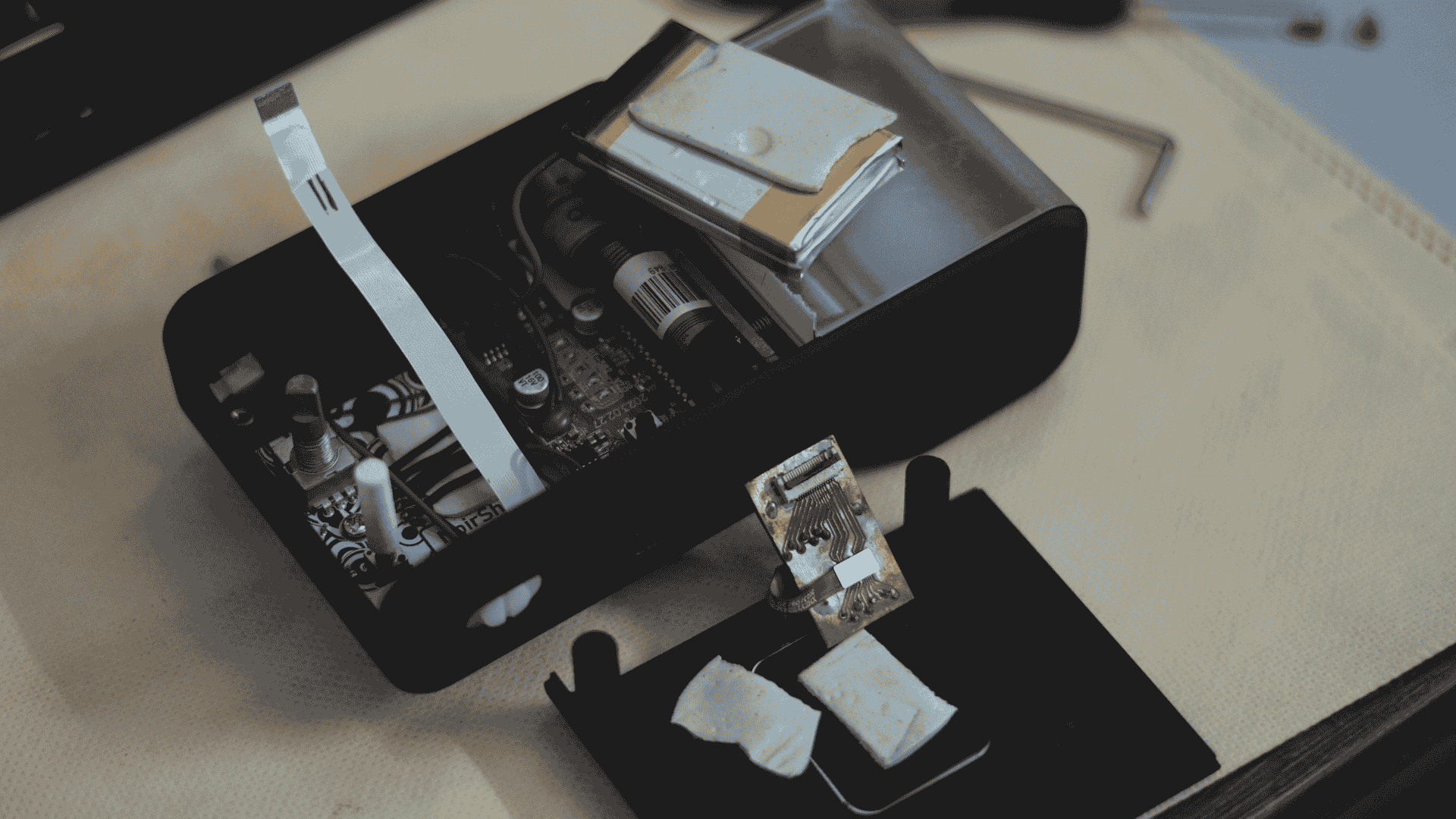
The entire unit runs off a single 7.4 V LiPo battery—originally from the thermal printer itself. It’s a dual-cell pack rated at 1500 mAh / 11.1 Wh, housed inside a plastic enclosure. I repurposed it by carefully prying it open, preserving the native power architecture. Since the printer circuitry is designed around this specific battery, it made sense to retain it for compatibility and simplicity.
Power distribution is handled by Rabin’s board, which includes onboard charging and voltage regulation. It steps down the 7.4 V input to supply both 5 V for the thermal printer and 3.3 V for the ESP32. This avoids needing separate regulators or power paths for different components.
There are two USB ports:
- One is the original USB port from the printer board. It supports both charging and external printing, acting as a host interface.
- The second USB is used to charge the battery and program the CH32 MCU—useful for future firmware updates.
I didn’t go for swappable cells. The battery is fixed internally and recharges like any modern portable device. Runtime hasn’t been fully stress-tested, but under typical usage, it easily lasts through a full day—and possibly multiple days—depending on print frequency.
Controls & UI
The device is operated using three tactile inputs, designed for a retro, no-fuss shooting experience:
- Trigger: Captures an image instantly.
- Rotary Knob (with press): Used for navigating prompts on the display and confirming selections.
- “A” Button: A context-aware multipurpose button, reserved for future UI features or shortcuts.
There’s no touchscreen input—intentionally. The UI is minimal by design, evoking the feel of vintage point-and-shoot cameras. You navigate one action at a time. No swiping, no zooming, no filters.
The display is a 1.69” IPS TFT, capable of touch input, but touch functionality is currently disabled to keep the UX straightforward. However, the CH32 microcontroller has the necessary touch pins mapped, so future firmware could enable touch if needed.
User Experience:
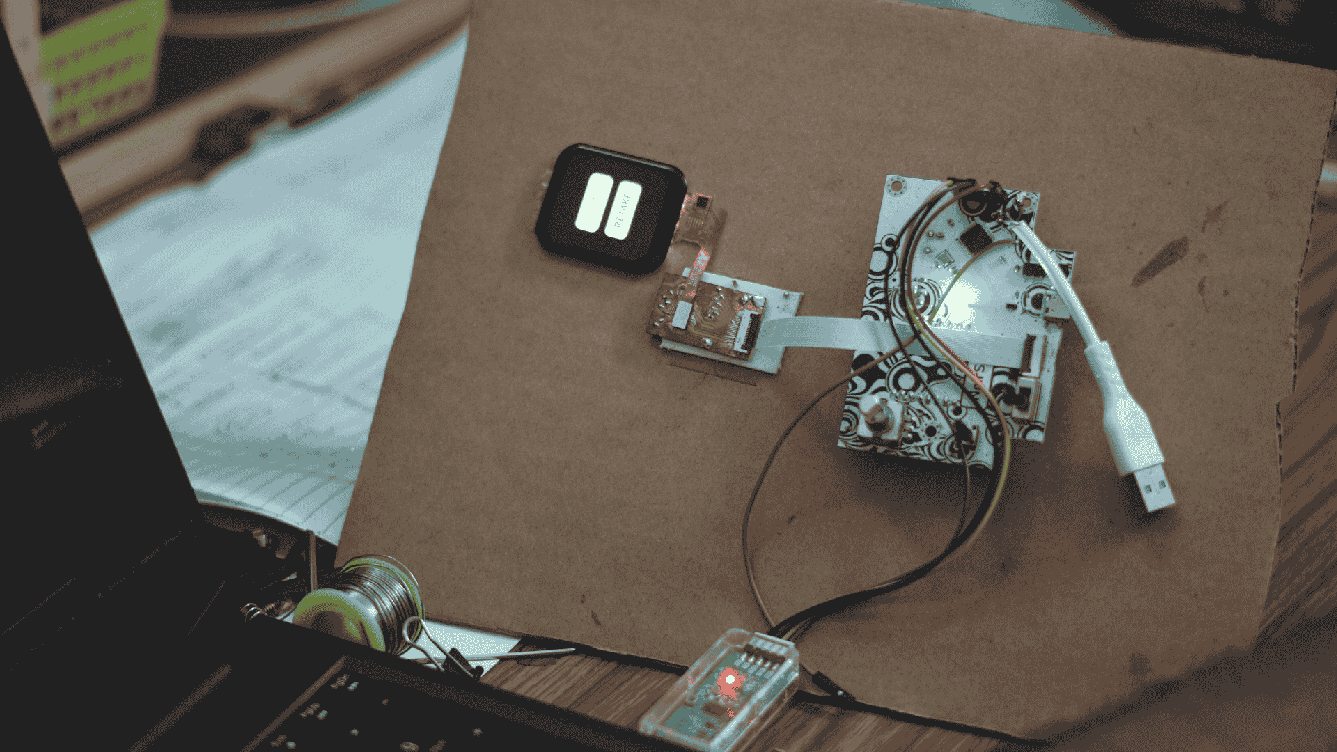
- Upon powering on, the UI prompts you to point and shoot.
- After capture, it immediately asks: Print or Retake.
- There’s no image browsing, no gallery, no edits—just quick capture and print.
- Images are pre-processed using a custom dithering pipeline, optimized specifically for the thermal printer’s output.
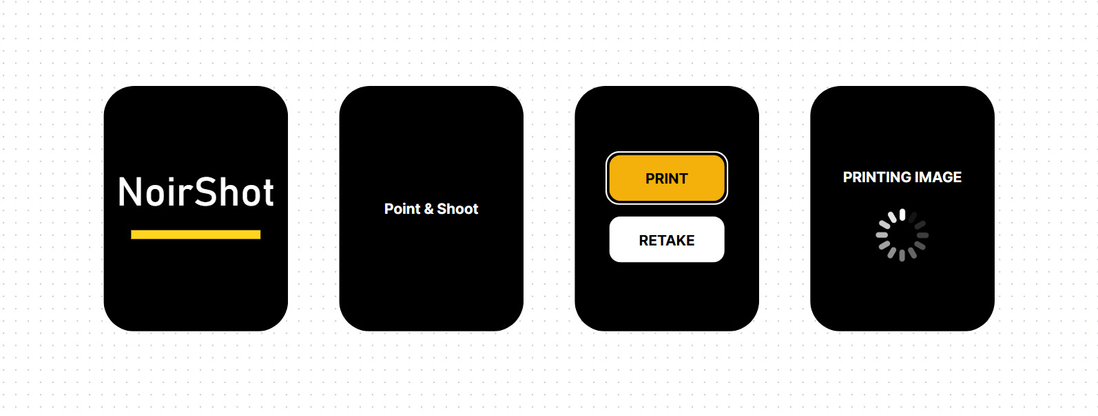
The result is a fast, focused, and intentionally limited experience—a digital instant camera with just enough control to keep it fun.
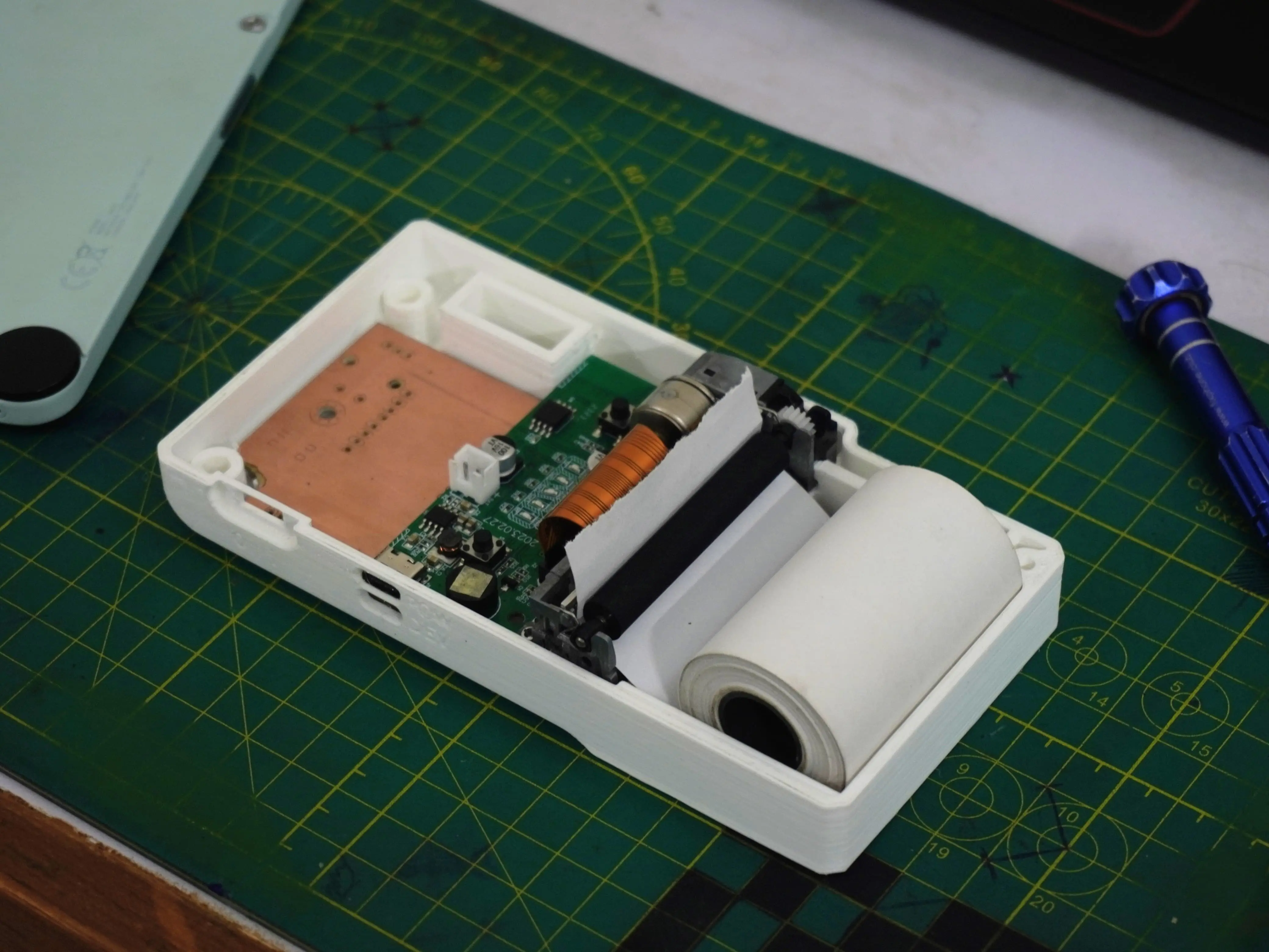
Prototyping: Precision Modeling & Fit Checks
The most critical mechanical challenge was the thermal printer’s feed mechanism. It requires consistent pressure on the print head and a precisely aligned paper path—any misalignment or tightness can lead to jams or skewed output.
To validate the fit early, I printed a sectional prototype of just the lower body—enough to check how the printer, battery, and electronics seated. Beyond that, I didn’t rely on iterative prints. Instead, I invested time in precise 3D modeling, measurement, and planning to ensure things worked right the first time.
That up-front modeling also helped refine the magnetically latched paper cover. Instead of hinges or clips, I used small neodymium magnets press-fit into designed cavities—clean, reliable, and easy to assemble.
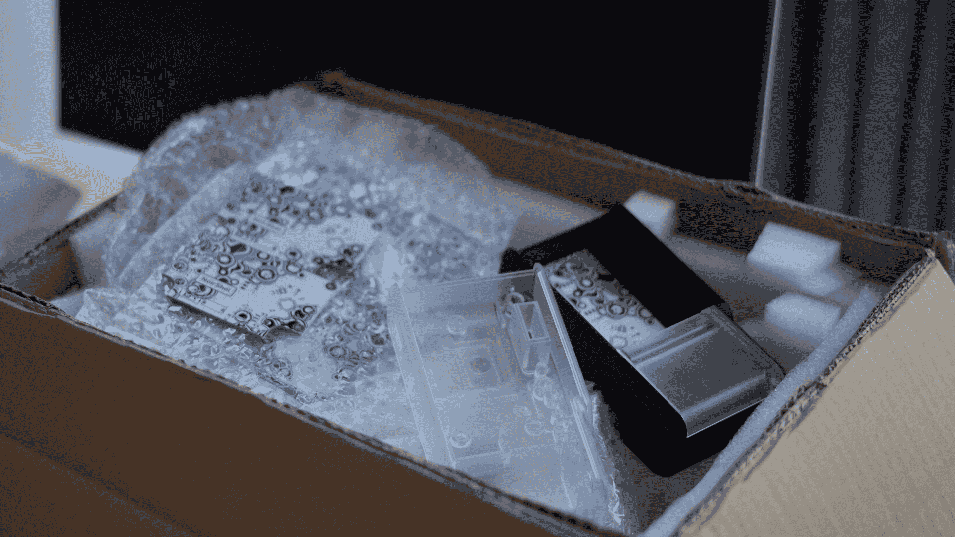
Final Assembly & Print Material
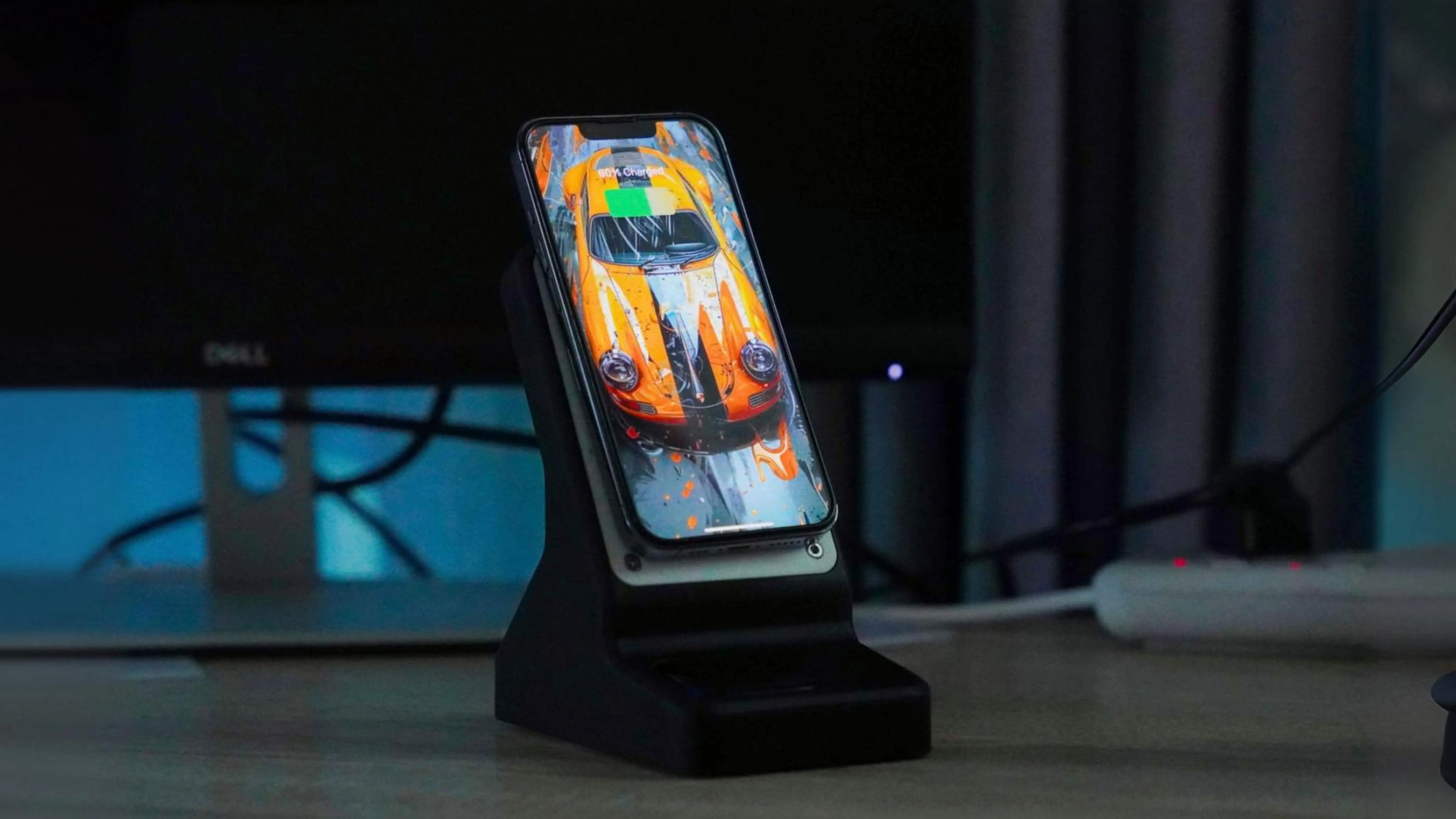
The final enclosure was manufactured through JLC3DP, who also sponsored my wireless charging dock project. Their resin prints delivered exactly what I needed: sharp detail, dimensional accuracy, and a clean finish right out of the box. This wasn’t my first time working with them, and again, their consistency impressed me. The prints were precise to spec, and seeing the design come to life with that level of quality never gets old.
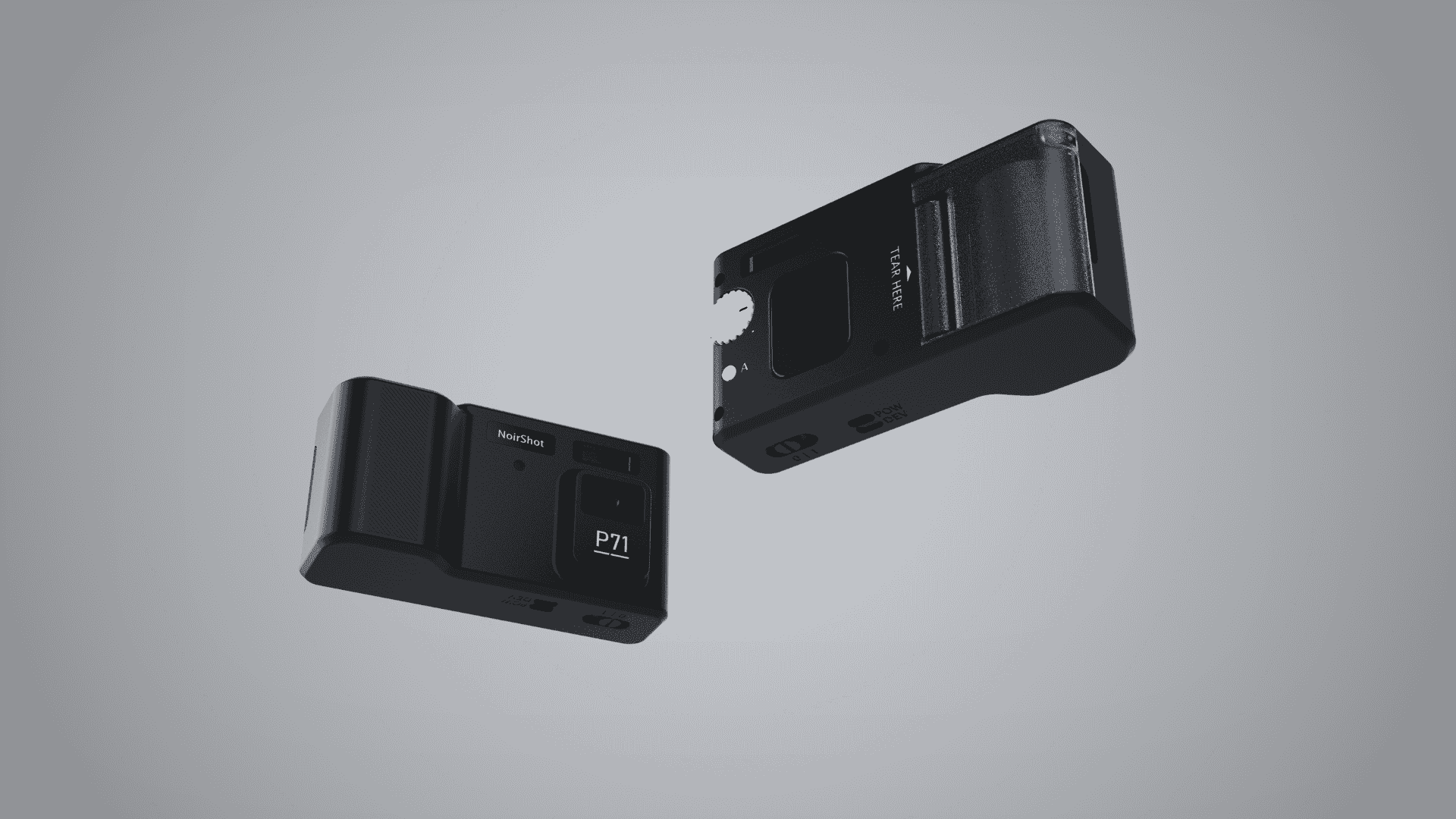
I experimented with two aesthetics:
- A black resin body paired with a translucent paper cover, white knobs, and white buttons.
- A fully translucent body contrasted by black knobs and black buttons. Both looked great and offered very different personalities—one more minimal and sleek, the other more playful and experimental.
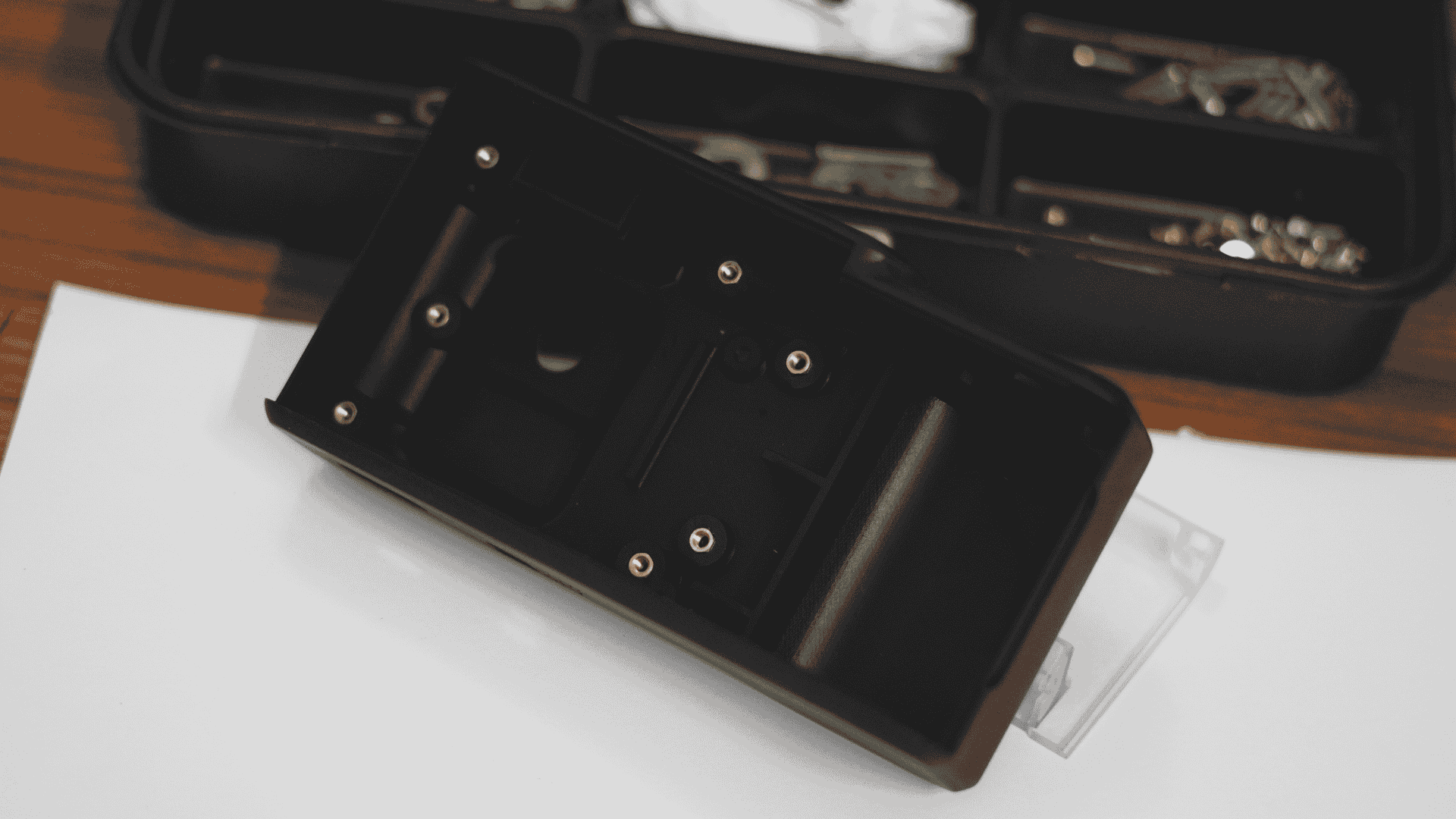
The enclosure is made of three major parts:
- Main body – houses all electronics and includes printed bosses for mounting. I glued M3 brass hex nuts for securing both the internal PCBs and the outer shell.
- Rear shell – attaches with M3 screws and holds the display module.
- Paper cover – magnetically attached using press-fit neodymium magnets. No hinges, no clips—just a satisfying snap into place.
Viewfinder & Acrylic Details
There’s a functional viewfinder window, not an optical one—just a clear acrylic cutout aligned to give a rough framing reference since the display doesn’t show a live feed (to keep the system fast and simple).
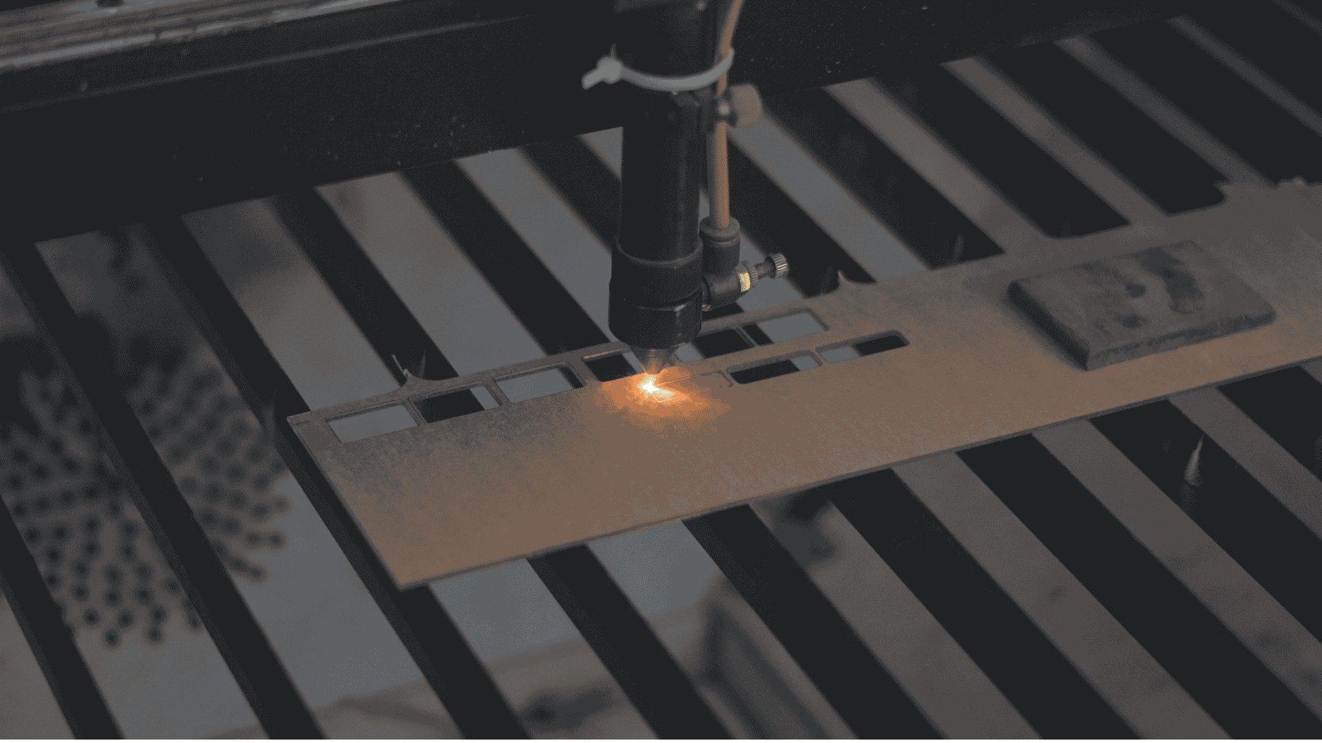
Other laser-cut acrylic elements include:
- A black-painted camera window and indicator LED window
- A custom “NoirShot” logo badge, created by laser-etching away paint on 2 mm acrylic, backed with white paper, and adhered to the case.
These accents add depth and sharpness to the design, making the whole device feel deliberate and finished.
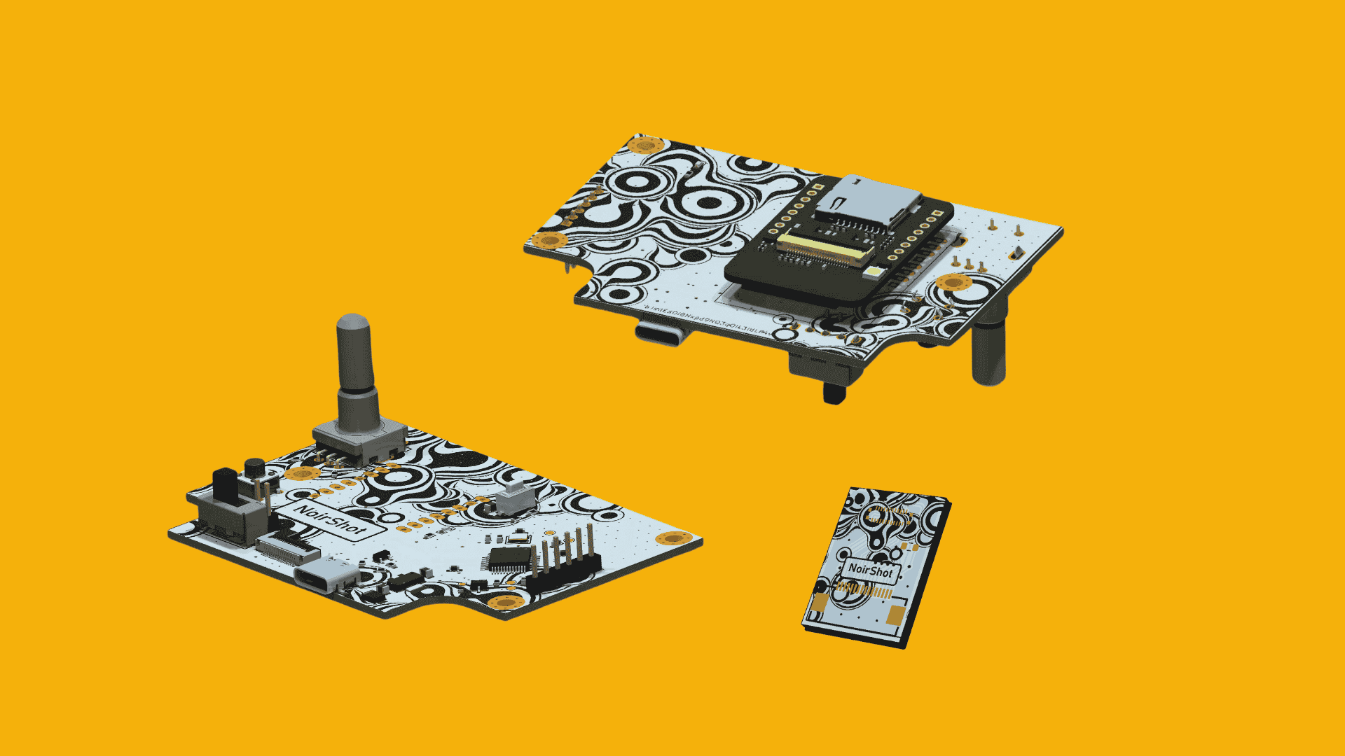
PCB & Electronics Mounting
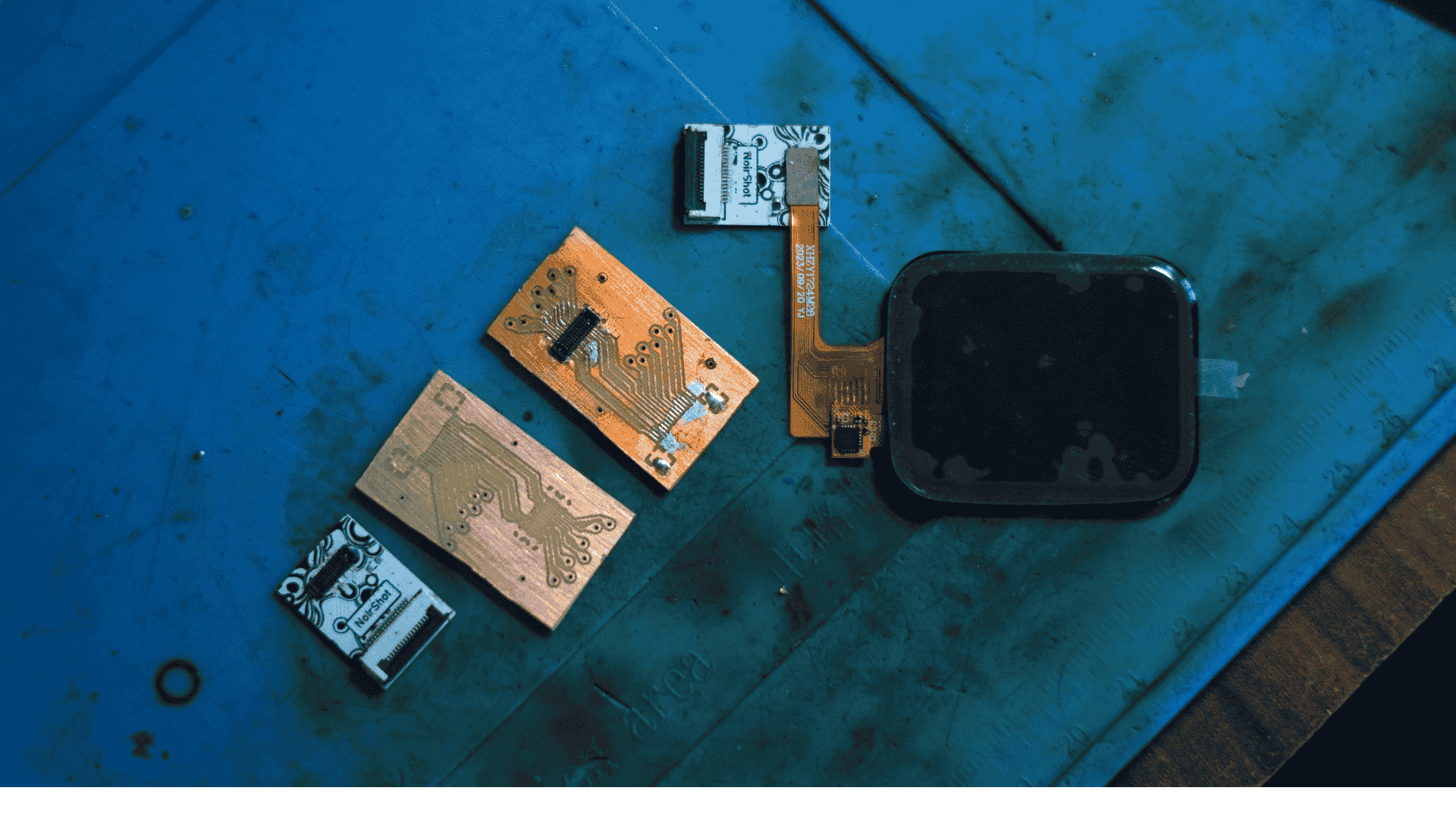
There were two custom PCBs:
- A main board with all the core electronics.
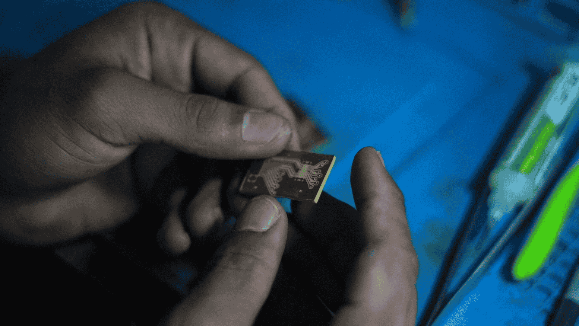
- A daughterboard that connects to the display via a 0.5 mm pitch 16-pin FPC connector.
To reduce risk during assembly—especially given how finicky that connector is—I isolated the FPC onto its own small board. That turned out to be the right call: the solder pads on the initial daughterboard were slightly short and not well-exposed, which made soldering unreliable. We eventually made a revised version of the daughterboard in-house, which worked fine for this prototype. I’ll order a corrected revision later.
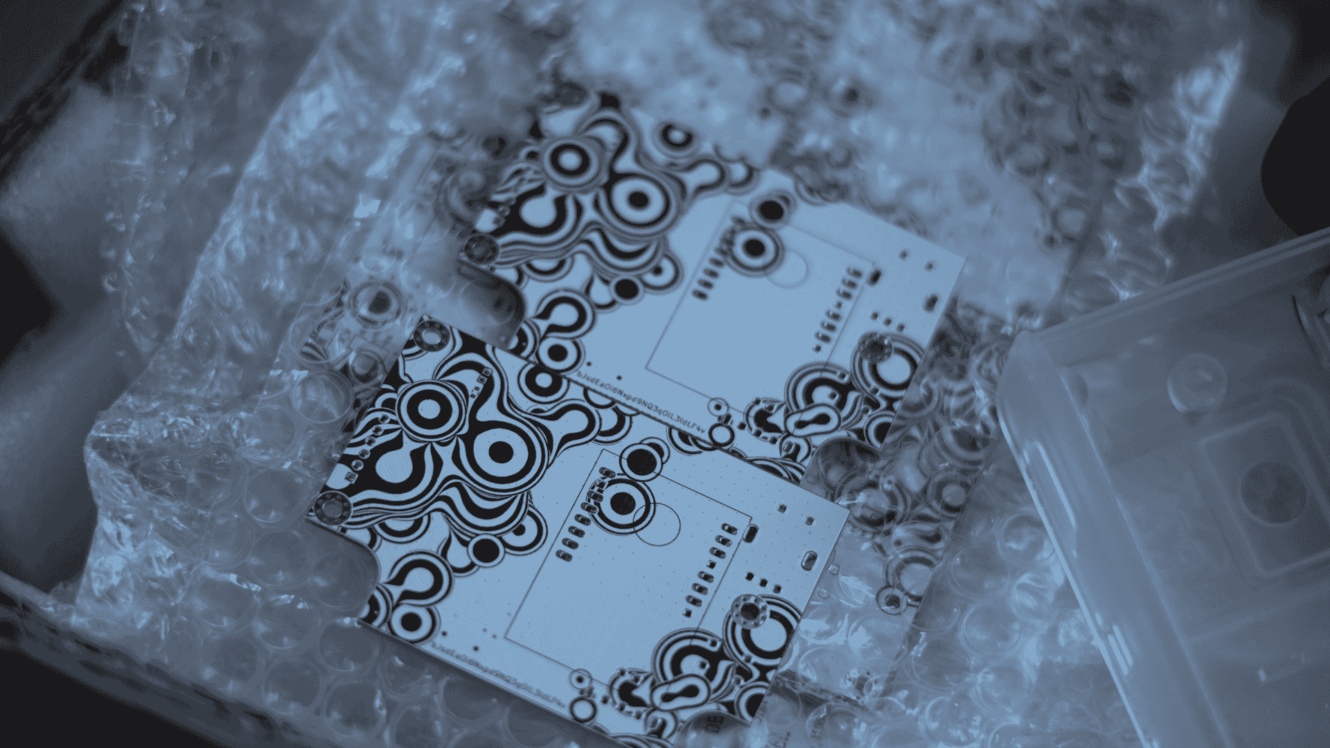
The main PCB includes a bit of visual flair as well: I added a custom artwork to the silkscreen, and JLC’s fabrication handled it beautifully—clean, crisp, and just the right touch of personality.
The whole assembly is screw-fastened—no glue, no tape. The interior is modular and serviceable, and everything locks together securely. No critical design flaws showed up in the final build, aside from the FPC pad issue on the daughterboard. Overall, it went together cleanly—and the result looks crisp, functional, and solid in hand.
What’s Next?
This was a collaborative build—I focused on the mechanical design and prototyping, while Rabin handled the electronics and firmware. His side of the project dives deep into the custom board design, image processing, and how everything’s stitched together in code. Definitely worth a look if you’re into embedded systems or DIY cameras.
The camera works as intended and is genuinely fun to use, but there’s always room to improve—whether it’s refining the shell, optimizing the print flow, or exploring a V2 with better optics.
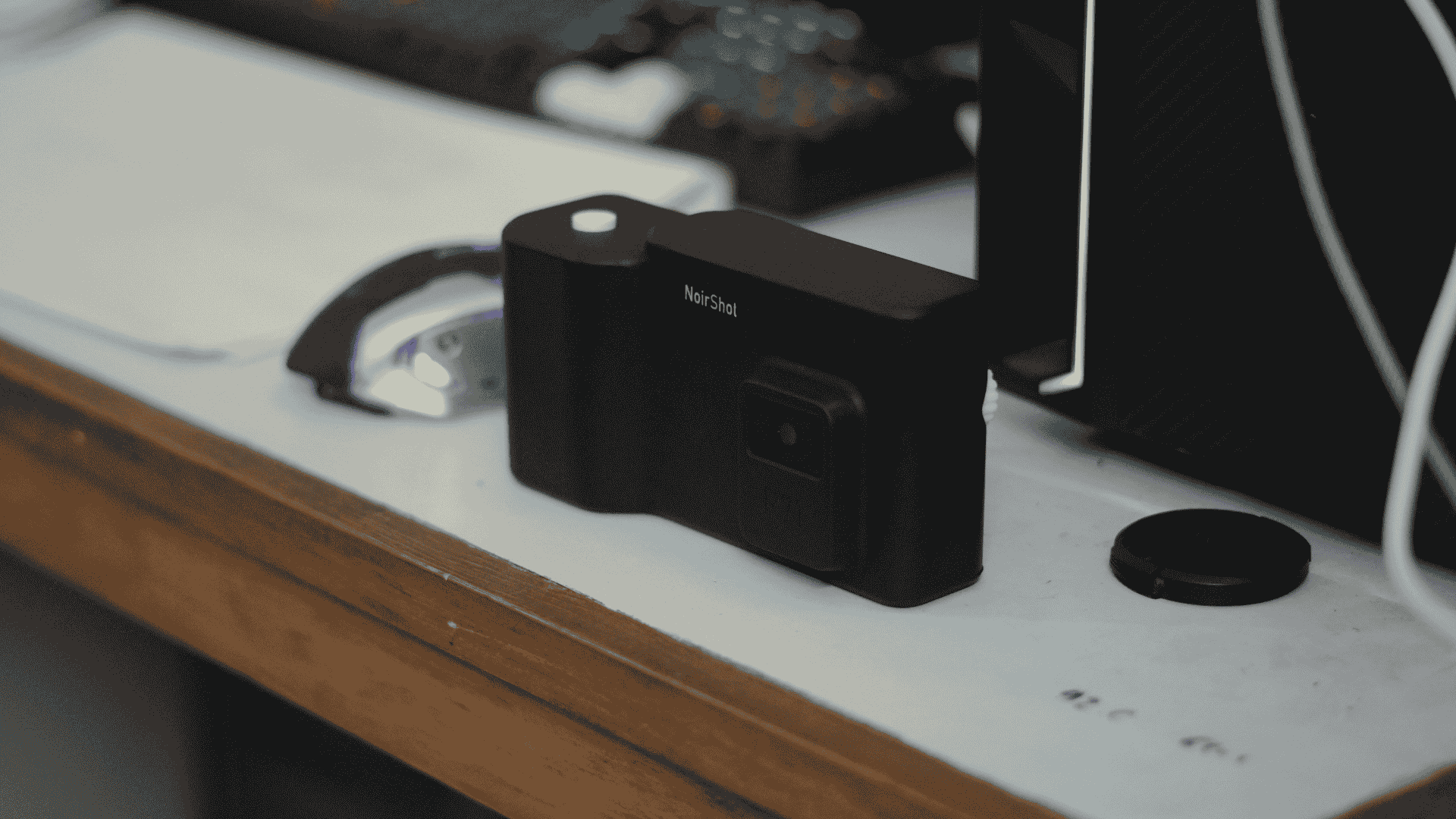
For now, NoirShot lives on my desk, ready to immortalize dumb moments in grainy, low-fi thermal glory.
